Output Devices
Semana 10: OUTPUT DEVICES Cindy Marilyn Crispin
GROUP ASSIGNMENT
Group Task: Measure Energy Consumption - Group Task
Group Assignment: Measuring Energy Consumption
To determine the power consumption of the components used in my project based on the board with ATmega328, it is necessary to measure two fundamental electrical variables: current (I) and voltage or voltage (V).
The electrical power consumed is calculated using the formula:
donde:
P = Power in watts (W)
V = Voltage in volts (V)
I = Current in amperes (A)
Current Measurement
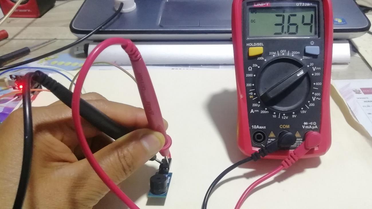
The current is measured in series with the circuit, connecting the multimeter between the power supply and the electronic board. The measurement is carried out while the system is running to obtain the actual energy consumption.
Voltage Measurement
The voltage is measured in parallel, placing the multimeter between the power terminals of the circuit. This allows us to know the voltage with which the system operates.
Análisis
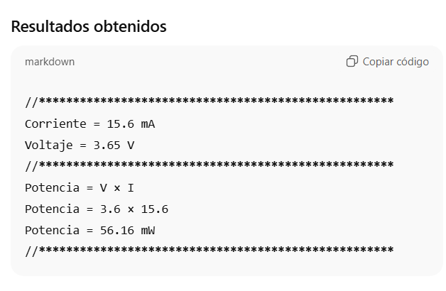
The results show that the energy consumption of the system is low, with an approximate power of 56.16 mW. This shows that the circuit has efficient operation and can operate with small power supplies.
Application in the Project
This system is part of a smart pot, designed to monitor the status of a plant using different electronic components, including:
HL-69 Soil Moisture Sensor to measure the moisture level of the soil.
OLED screen to display information about the status of the plant.
This type of system allows you to improve plant care by automatically monitoring soil moisture, providing information to the user to know when it is necessary to water the plant.
Individual
Enlaces útiles
https://www.arduino.cc/
As an introduction, some code examples that work with Arduino software and hardware are presented. These codes allow a practical understanding of the basic operation of the platform and its interaction with the electronic components. The step-by-step process for its implementation and execution within the development environment will be described later.
Galería
First of all, the official Arduino website was accessed with the aim of exploring the different tools that this platform offers, both in software and hardware. Arduino is one of the most used electronic development platforms at an educational and professional level, due to its ease of use, its active community and its extensive documentation.
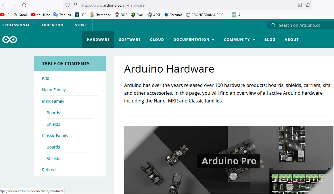
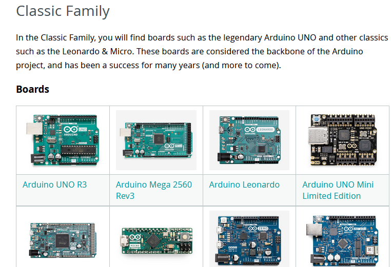
Subsequently, the section corresponding to the classic family of Arduino boards was visited. In this section you can find various models such as Arduino Uno, Arduino Mega, Arduino Nano, among others, each with specific characteristics according to the needs of the project to be developed.
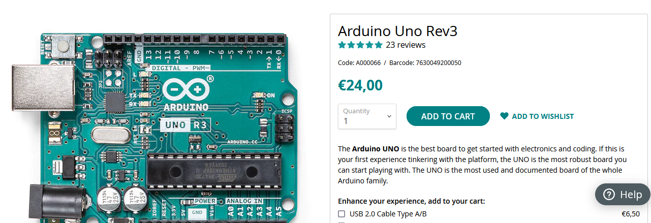
The following image shows the Arduino Uno board, which was selected to analyze its characteristics and technical specifications. This board is one of the most used in learning and rapid prototyping projects.
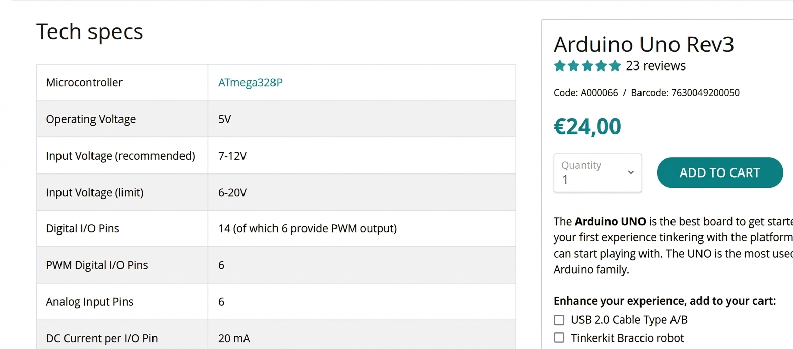
The figure shows the technical specifications of the Arduino Uno, where it can be seen that this board works with the architecture based on the ATmega328P microcontroller, a component widely used in embedded systems.
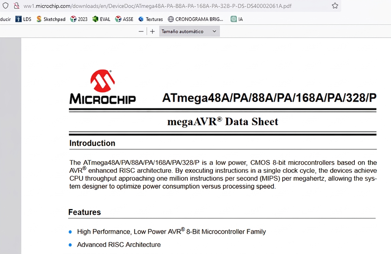
By accessing the corresponding link, you can consult the ATmega328P technical manual, a document that describes in detail the internal architecture and operation of this microcontroller. This manual is essential to understand how the internal resources of the system are managed.
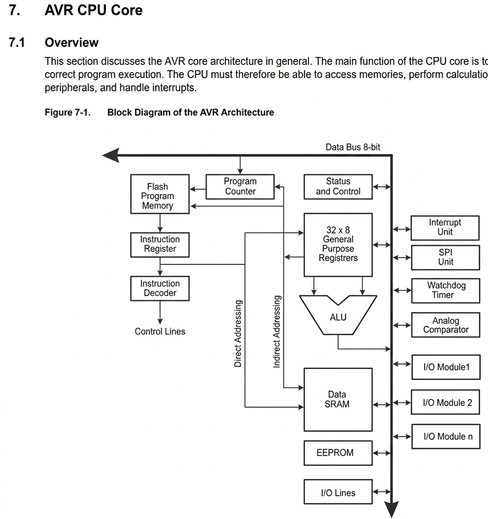
This section analyzes the architecture of the AVR core, which constitutes the basis of operation of the microcontroller. The main function of the CPU core is to ensure the correct execution of the program stored in memory. To do this, the CPU must be able to access memory, perform arithmetic and logical operations, control peripherals, and manage system interrupts.
.
Likewise, the main characteristics of the microcontroller are presented, highlighting its processing capabilities, management of digital and analog inputs and outputs, as well as its internal timing modules.
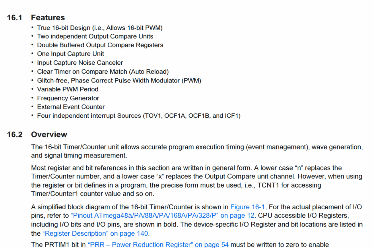
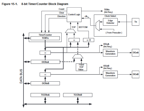
One of the important modules is Timer/Counter0, which corresponds to a general purpose 8-bit timer/counter. This module has two independent output comparison units and support for PWM signal generation. Thanks to this system, it is possible to make precise timings within the execution of the program, manage events and generate different types of signals.
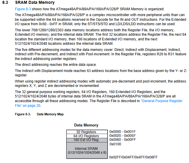
The structure of the main memory used by the microcontroller is also described, where both the program instructions and the data necessary for its execution are stored.
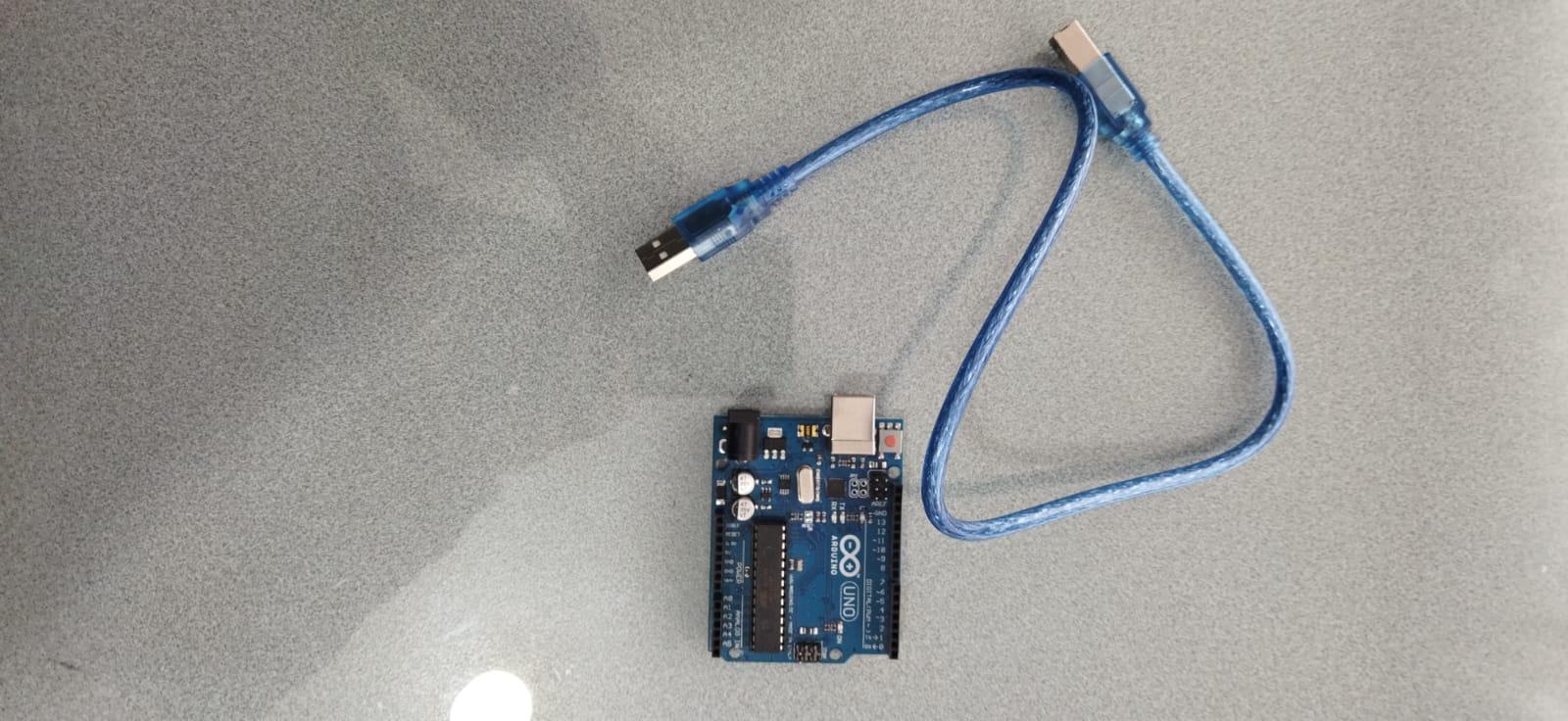
Next, the practice begins using the Arduino Uno hardware along with its respective USB connection cable, which allows communication between the board and the computer.
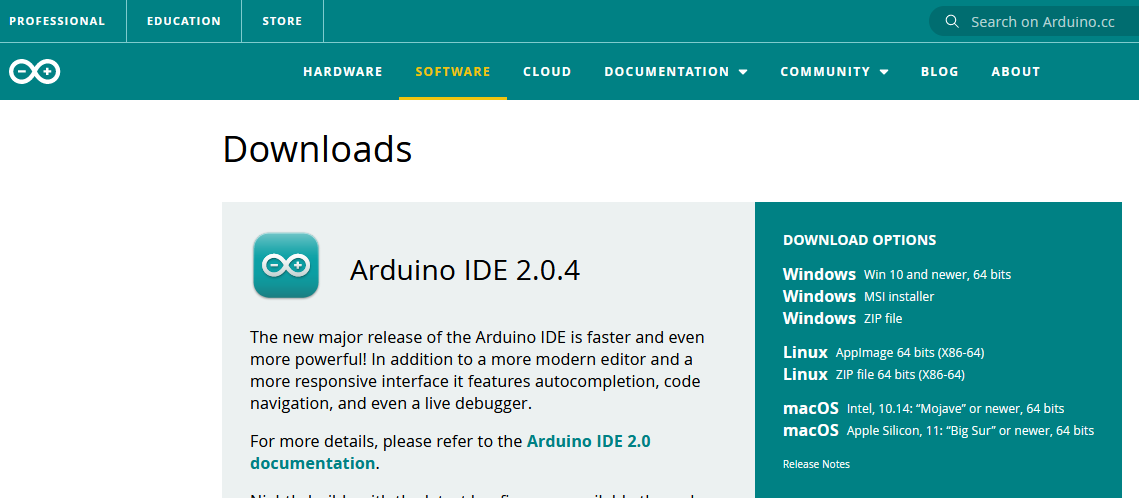
Subsequently, the official Arduino page was accessed again, specifically the software section, to proceed with the download of the Arduino IDE development environment.
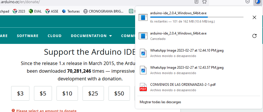
During the download process, it is noted that the software is completely free; However, the page offers the possibility of making a voluntary contribution to support the development of the project.

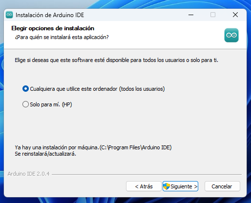
Once the file is downloaded, the installation process begins in the Windows operating system, following the steps indicated by the installation wizard.
At this stage, the option is selected that allows any computer user to use the installed program.
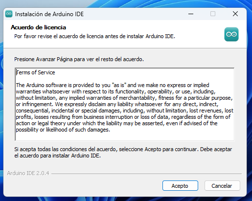
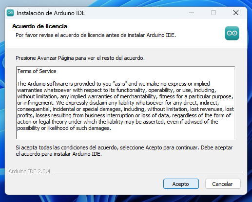
Subsequently, the conditions and terms established by the software are accepted to continue with the installation
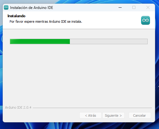
Next, the Windows operating system proceeds to install all the files necessary for the correct functioning of the Arduino IDE.
Finally, the installation process is completed successfully and the program is run to start working with the platform.
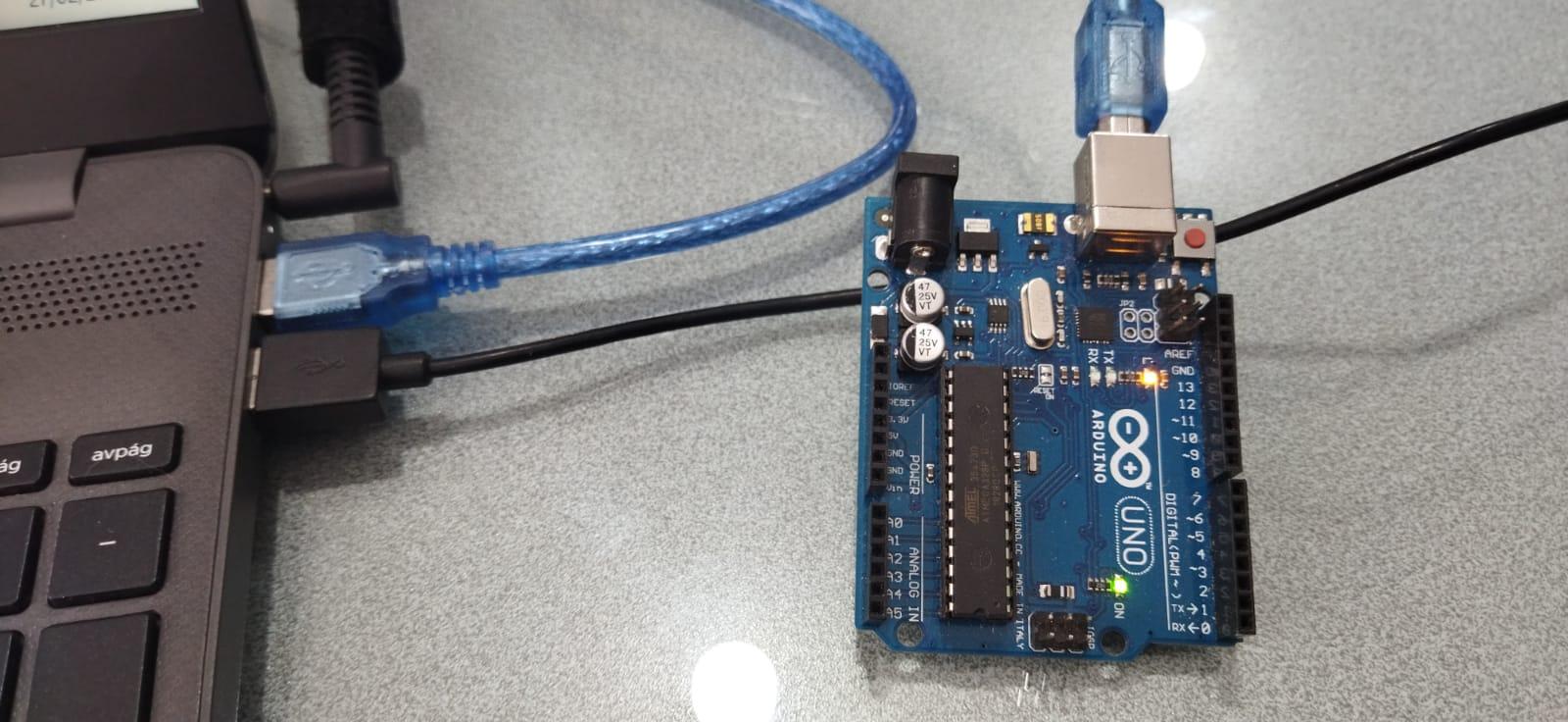
Next, the Arduino board is connected to the laptop using the USB cable, allowing the system to automatically detect the device.
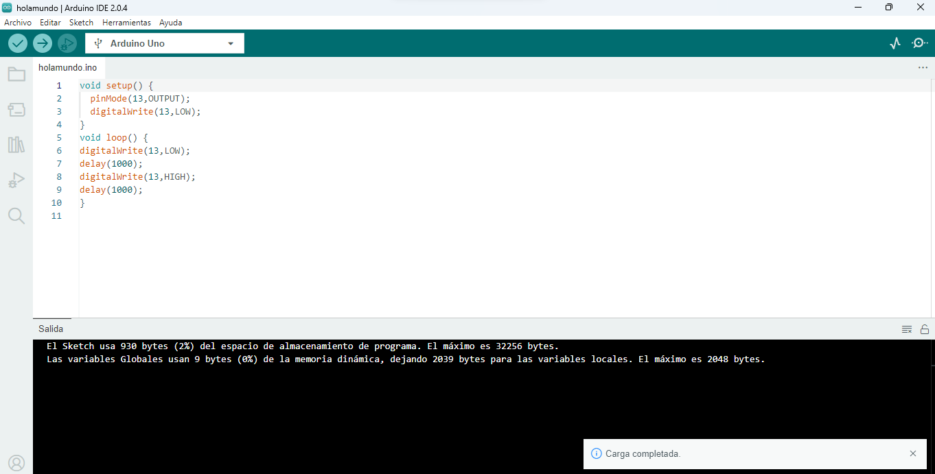
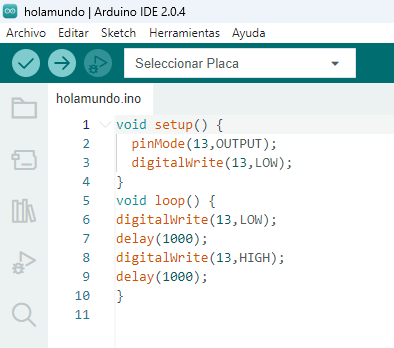
Once the connection is established, we proceed to program in C language within the Arduino environment, using the classic “Hello World” example, which consists of turning on and off the LED integrated into pin 13 with a waiting interval of one second.
.
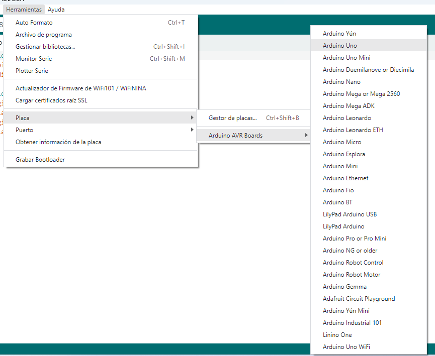
Within the Arduino IDE, the configuration of the board to be used is carried out, selecting the Arduino Uno model from the tools menu.
.
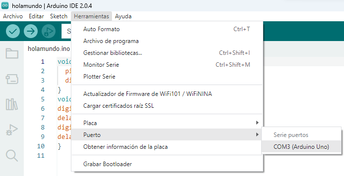
Subsequently, the corresponding communication port is configured, in this case COM3, which allows communication between the computer and the Arduino board.
Finally, the code is uploaded to the Arduino board. The system carries out the compilation and loading process of the program, displaying a confirmation message indicating that the code was loaded correctly and without errors.