Machine Design
WEEK 12: MECHANICAL DESIGN AND MACHINE DESIGN
Mechanical Design & Machine Design
Mechanical design and machine design
This week we worked on the development of a functional machine designed and built as a team, integrating mechanical, electronic components and automation systems.
The main objective was to design a mechanical system that includes a functional mechanism, an actuation system, an automation method and a practical application. This process allowed the application of design concepts, digital manufacturing, electronic integration and collaborative work.
The development of the machine involved several stages, including:
Diseño conceptual
Mechanical system planning
Manufacturing of parts
Mechanism assembly
Integración electrónica
System automation
This process allowed us to understand how the different elements of a machine interact with each other to generate movement and perform a specific function.
Group Assignment
Collaborative work in the design of the machine
The development of the machine was carried out as a teamwork project, where each member contributed at different stages of the design and manufacturing process.
The team worked in a coordinated manner to define the initial idea of the machine, analyze possible mechanical solutions and select the components necessary for its construction.
During this phase, different proposals were discussed until reaching a viable solution that could be manufactured using the tools available in the Fab Lab.
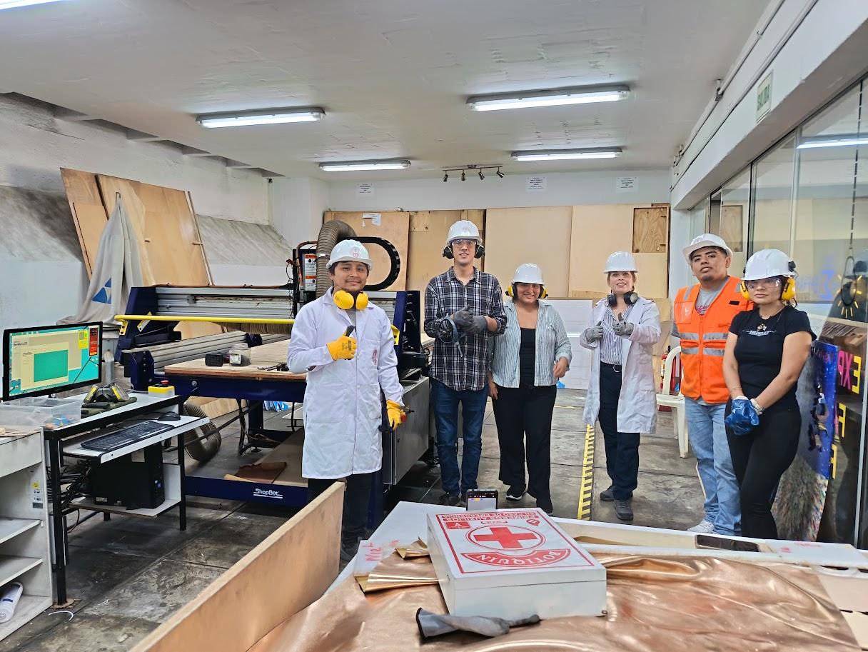
Photo of the team working or meeting
Individual contribution – Machine design
Automatic piggy bank with PIR sensor and ATmega328 microcontroller
As part of my individual contribution to the Mechanical Design and Machine Design project, I developed a working prototype of an automated interactive piggy bank, which integrates mechanical design, electronic sensors and microcontroller control.
The objective of this project was to design a system that combines digital manufacturing, electronics and automation, allowing the object to interact with the user through motion detection and visual response.
The developed machine consists of a piggy bank manufactured by 3D printing in PLA filament, equipped with a PIR motion sensor and an LED lighting system controlled by an ATmega328 microcontroller. When the sensor detects movement near the piggy bank, the system automatically activates the LED lights, generating a visual response that indicates the user's interaction with the device.
This prototype demonstrates how it is possible to integrate mechanical structure, sensors and programming to create intelligent devices that respond to the environment.
System mechanical design
The mechanical design of the piggy bank was developed using 3D modeling software, considering both the functionality of the object and the integration of the electronic components within the structure.
The model was designed to include different internal spaces that allow the electronic components to be housed without affecting the stability of the system.
La estructura incluye:
Top slot for inserting coins
Internal compartment for storage
Space for PIR sensor
Internal support for ATmega328 microcontroller
Holes for installing LEDs
Removable lower base for maintenance
This approach allowed us to design a compact system in which the electronics are protected within the mechanical structure.
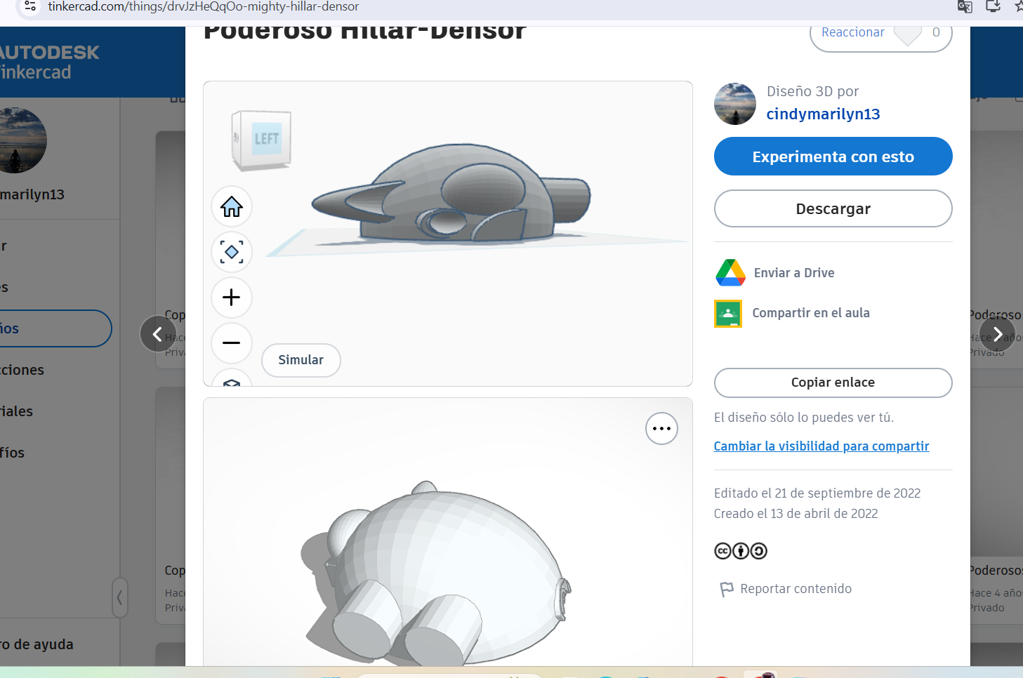
3D model of piggy bank in design software. Image description: Digital design of the piggy bank showing the spaces designated for the PIR sensor, the ATmega328 microcontroller and the LED lighting system.
Fabricación mediante impresión 3D
Once the model design was completed, the file was exported in STL format and prepared for manufacturing using a 3D printer.
The material used was PLA (polylactic acid), a filament widely used in prototyping processes due to its ease of printing, good resistance and low environmental impact.
Manufacturing using 3D printing made it possible to materialize the digital design and obtain a functional structure ready to integrate the electronic system.

Photo of the 3D printing process. Image description: Piggy bank manufacturing process through 3D printing using PLA filament.
Photo of the finished piece. Image description: Piggy bank structure printed in PLA after the manufacturing process.
Sistema electrónico
The electronic system was designed to allow motion detection and automatic activation of the lighting system.
The components used in the project were:
Microcontrolador ATmega328
PIR motion sensor (Passive Infrared Sensor)
Luces LED
Current limiting resistors
Power supply
The PIR sensor detects changes in infrared radiation produced by the movement of a person in front of the device. When the sensor detects presence, it generates a digital signal that is sent to the ATmega328 microcontroller.
The microcontroller processes this signal and activates the LED lighting system for a certain time.
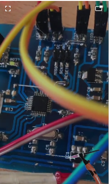
Photo of the electronic components used. Image Description: Electronic components used for the piggy bank detection and activation system.
Circuit connection
The PIR sensor was connected to one of the digital pins of the ATmega328 microcontroller. The sensor output signal is constantly monitored by the microcontroller program.
When the sensor detects movement, the microcontroller activates the outputs corresponding to the LEDs, generating a visual effect that indicates that the system has detected interaction.
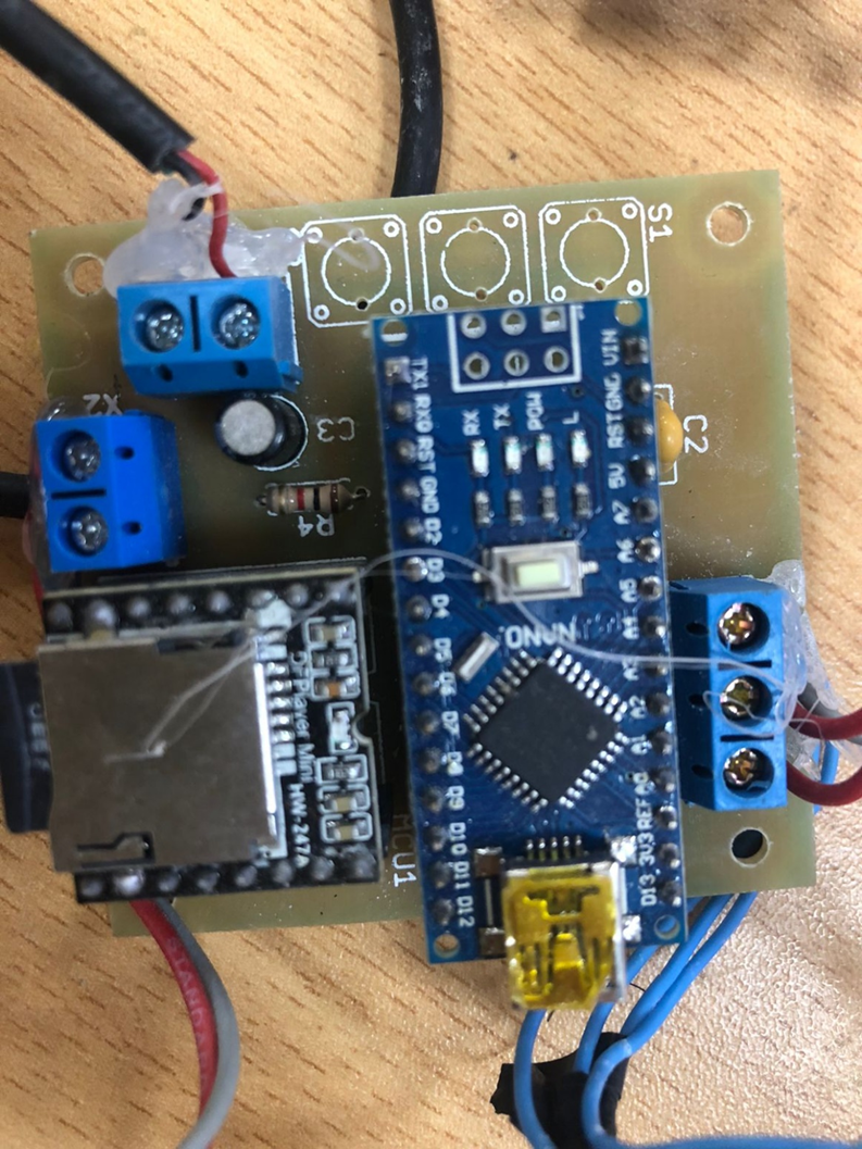
Photo of the assembled circuit. Image description: Assembly of the electronic circuit that connects the PIR sensor with the ATmega328 microcontroller and the LED lights.
System programming
The behavior of the system was defined by programming the ATmega328 microcontroller.
The program continuously reads the PIR sensor. When the sensor detects motion, the system activates the LED lights for a few seconds and then turns them off automatically.
This process allows the system to work autonomously, without the need for direct user intervention.
System Integration
Once the correct operation of the electronic circuit was verified, all the components were integrated into the structure of the piggy bank.
The PIR sensor was placed on the front of the device to allow efficient detection of the user's movement. The LEDs were positioned in visible areas to generate a visual effect when the system is activated.
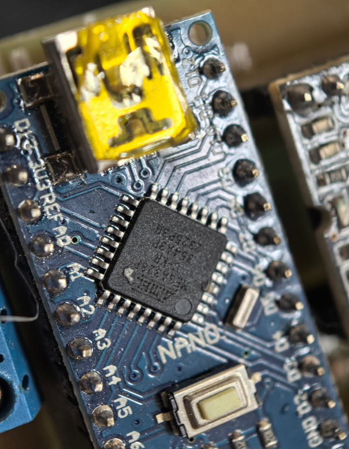
Photo of the internal assembly. Image Description: Integration of PIR sensor, ATmega328 microcontroller and lighting system inside the piggy bank.
Machine operation
The operation of the system is based on the interaction between the motion sensor and the microcontroller.
The process occurs as follows:
The user approaches the piggy bank or inserts a coin.
The PIR sensor detects movement in its coverage area.
The sensor sends a digital signal to the ATmega328 microcontroller.
The microcontroller processes the signal and activates the LED lights.
After a few seconds, the system automatically turns off the LEDs.
This behavior turns the piggy bank into an interactive device that responds to the user's presence.
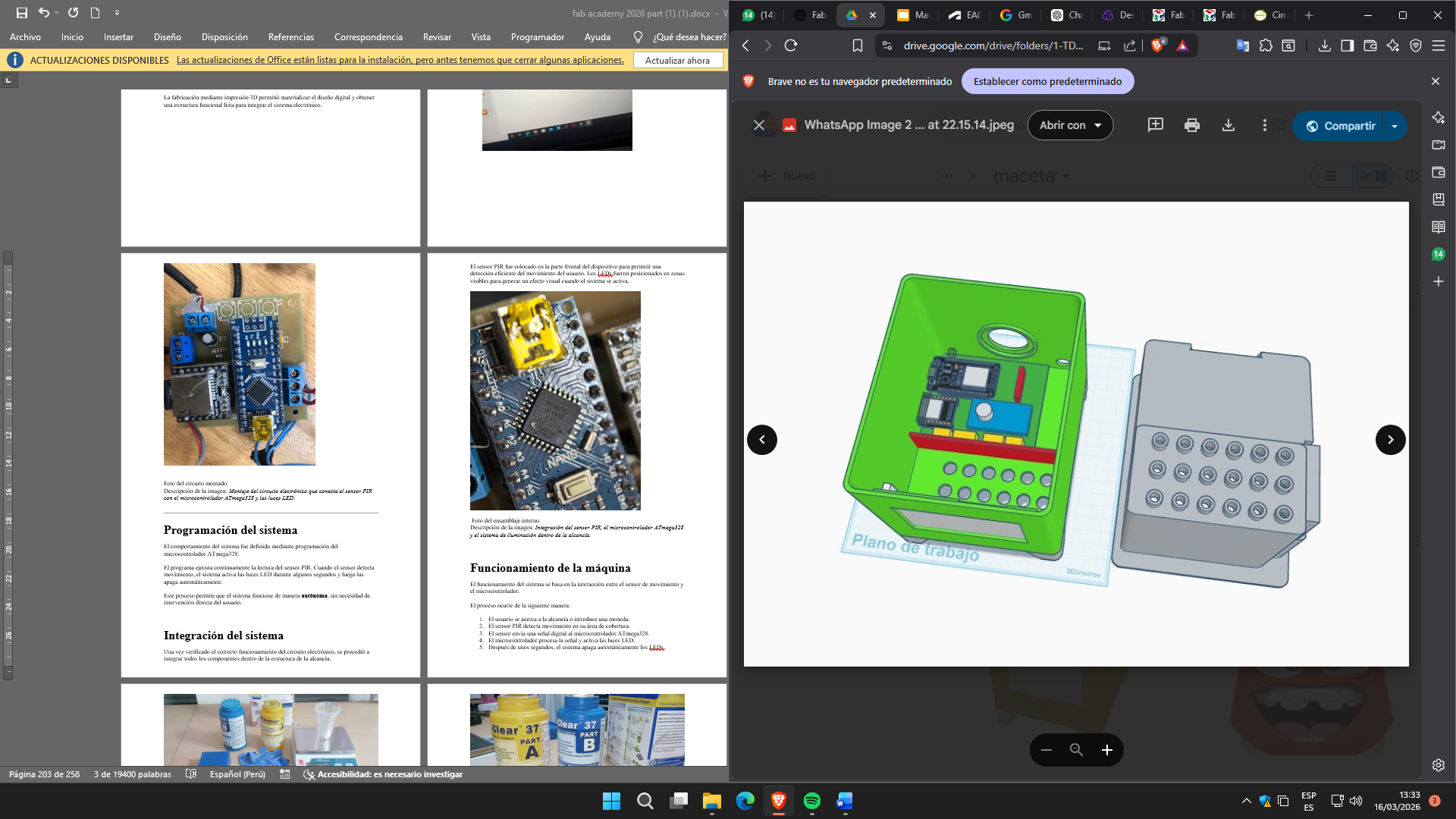
Photo of the system working. Image Description: Activation of LED lights when the PIR sensor detects movement in front of the piggy bank.
Problemas encontrados y soluciones
Some technical challenges arose during the development of the prototype.
One of the main problems was the layout of the internal space for the electronic components, which required adjustments to the 3D design to ensure that all elements could be correctly integrated within the structure.
It was also necessary to adjust the position of the PIR sensor to improve the detection of movement in front of the device.
These problems were solved through iterations in the design and testing of the system.
Posibles mejoras
Although the prototype fulfills its main function, some improvements were identified that could be implemented in future versions of the project:
Integration of a digital coin counter
Incorporation of RGB LED lighting for more dynamic visual effects
Implementation of a sound module to generate auditory feedback
Integration with IoT systems to record savings in an application
These improvements would expand the functionality of the device and improve the user interaction experience.