Electronics Production
Semana 04 Embedded Programming
(Fab Academy 2026 – Integrated Programming)
GROUP ASSIGNMENT
Programación integrada:
1. Atmega328p
The ATmega328/P is a low-power 8-bit CMOS microcontroller based on the AVR® enhanced RISC architecture. At execute powerful instructions in a single clock cycle, the ATmega328/P achieves performance close to 1 MIPS per MHz. This allows system designer to optimize the device for power consumption versus processing speed High-performance, low-power Atmel®AVR® 8-bit microcontroller family • Advanced RISC architecture – 131 powerful instructions – Increased single clock cycle execution – 32 x 8 general purpose work logs – Completely static operation – Up to 20 MIPS performance at 20 MHz – On-chip 2-cycle multiplier • High-endurance non-volatile memory segments – 32 Kbytes of self-programmable Flash program memory in the system – 1 Kbyte of EEPROM – 2 Kbytes of internal SRAM – Write/erase cycles: 10,000 Flash/100,000 EEPROM – Data retention: 20 years at 85°C/100 years at 25°C(1) – Optional boot code section with independent lock bits • In-system programming via on-chip boot program • Real read-while-write operation – Programming lock for Software Security • Atmel QTouch library support : capacitive touch buttons, sliders and wheels . Acquisition of QTouch and QMatrix : up to 64 detection channels. • I/O and packets : 23 programmable I/O lines : 28-pin PDIP, 32-lead TQFP, 28-pad QFN/MLF and 32-pad QFN/MLF.
https://www.datasheets.com/microchip/ATMEGA328P-PU
Individual Assignment
https://academy.cba.mit.edu/classes/embedded_programming/index.html
This week's topic was Embedded Programming, one of the most important stages within the digital manufacturing process, since it is the moment where the hardware comes to life. This week I not only worked with code, but I understood the deep relationship between the microcontroller, its physical limitations, and its processing capacity.
Los objetivos planteados fueron:
Read and interpret the data sheet of a microcontroller.
Program my board using as many programming languages and environments as possible.
My Work Plan
To correctly organize the development of the week, I structured my work as follows:
Understand the concept of embedded programming.
Analyze the microcontroller data sheet.
Programar mi placa utilizando diferentes entornos.
What is an Embedded Program?
An embedded program is software designed specifically to run inside a microcontroller and perform a specific function. Unlike traditional software, this type of program is conditioned by the limited hardware resources: memory, processing speed, energy consumption and number of available pins.
That is, it is not freely programmed; It is programmed by deeply understanding the device.
Datasheet del Microcontrolador: ATmega328P.
The microcontroller I used on my "Hello World" board was the ATmega328P, so I proceeded to carefully study its data sheet.
(space for datasheet image)
On the first page I found a general summary of its most relevant features:
8-bit AVR microcontroller.
Bajo consumo energético.
Hasta 120 instrucciones.
Memory retention up to 100 years at 25°C.
Operating voltage between 1.8V and 5.5V.
Industrial temperature range -40°C to 85°C.
Comunicación mediante interfaz SPI.
Programación ISP integrada.
The structure of the datasheet is organized in a technical and systematic way:
Pin configuration
Descripción general
Información adicional
Log Summary
Instruction Set
Order information
Packaging information
Errata
Revision history
Pin Configuration
The 14- and 20-pin packaging diagrams are shown in the “Pin Configuration” section (although the model used uses 14 active pins).
(space for pinout image)
Tres pines están destinados a:
VCC (alimentación)
GND (tierra)
RESET
The rest is divided into two ports:
Port A: 8 pin bi-directional analog input/output.
Port B: 4 pin bi-directional digital input/output.
Ambos puertos incluyen resistencias internas pull-up configurables.
In conclusion, I have 12 programmable pins (8 from port A and 4 from port B), which allows me to:
Leer hasta 8 señales analógicas.
Leer hasta 12 señales digitales.
Control multiple actuators depending on configuration.
Understanding this was key before writing any line of code. ATmega328P.datasheet.pdf
Programando Mi Placa
Materiales Utilizados
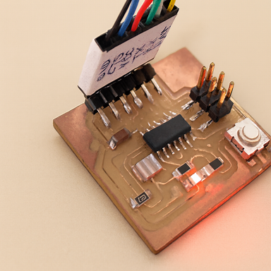
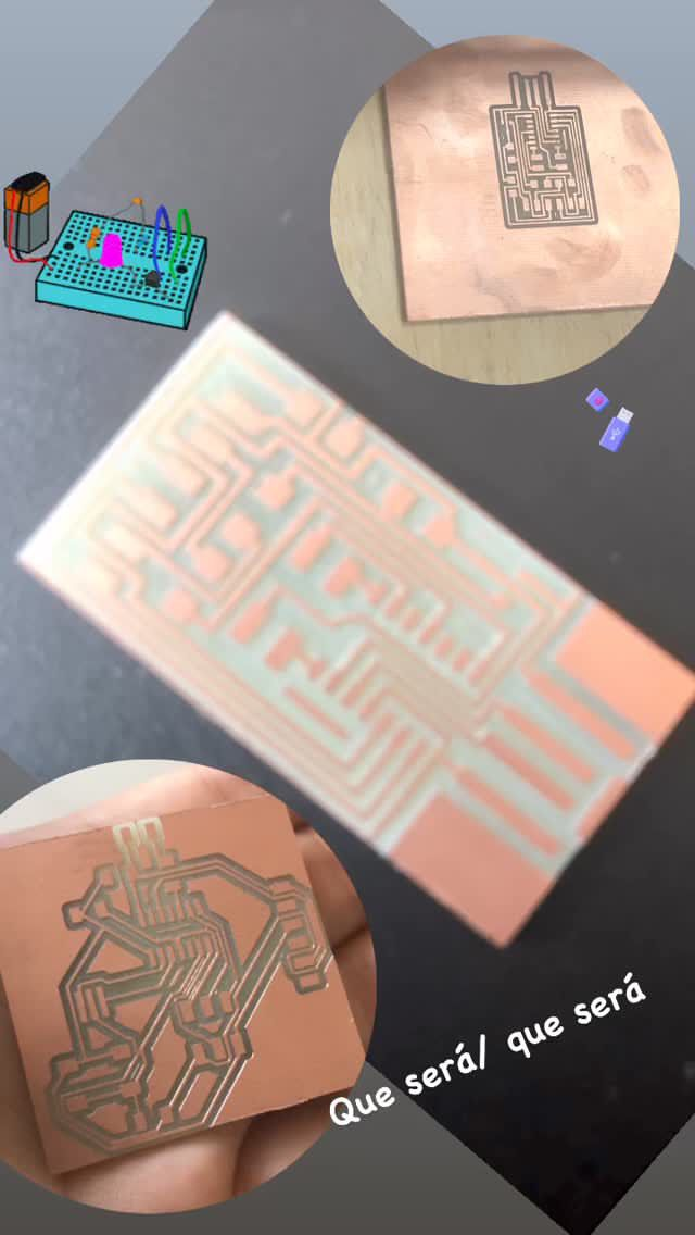
My PCB manufactured in electronic design task.
Mi programador FabISP.
6-wire flat cable.
Cable USB.
Cable FTDI.
Computer with USB ports.
Lenguajes Utilizados
The goal was to use as many languages as possible. In my case I worked with:
C/C++ desde Arduino IDE.
C desde Atmel Studio.
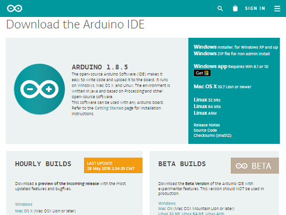
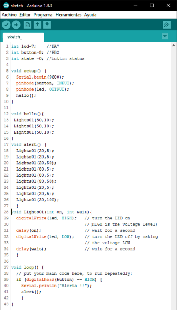
1. Programación desde Arduino IDE
First I downloaded the latest version of the IDE from the official Arduino site.
(space for image of the Arduino IDE)
The environment is divided into three main areas:
Top bar with tools.
Central editing area.
Build bottom console.
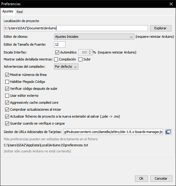
Like the ATmega328P. It is not included by default, I had to add the support manually.
Fui a:
Archivo → Preferencias
In “Manager of additional card URLs” I added:
https://raw.githubusercontent.com/damellis/attiny/ide-1.6.x-boards-manager/package_damellis_attiny_index.json
Luego ingresé a:
Tools → Board → Card Manager
I searched for “ATtiny” and installed the corresponding package.
Después seleccioné:
Herramientas → Placa → ATtiny24/44/84 Herramientas → Procesador → ATmega328P.
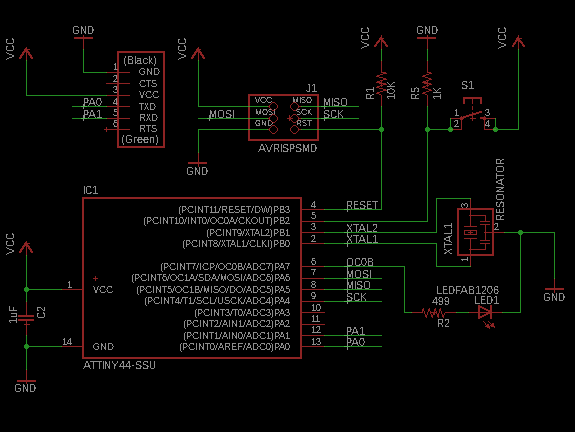
Pin Equivalence
En mi esquemático:
El LED está conectado al pin físico 6.
El botón está conectado al pin físico 5.
These do not correspond directly to the Arduino numbering, so I checked the equivalence table.
(space for equivalence table)
Pin físico 6 → PA7
Pin físico 5 → PB2
Understanding this conversion was essential for the code to work correctly.
Test Program
I designed a program with the following logic:
Upon startup, the LED flashes three times.
If the button is pressed, the LED performs the SOS sequence (three short, three long, three short).
Este ejercicio me permitió validar:
Correct pin configuration.
Use of digital inputs.
Use of delays and time control.
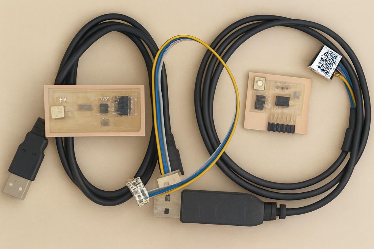
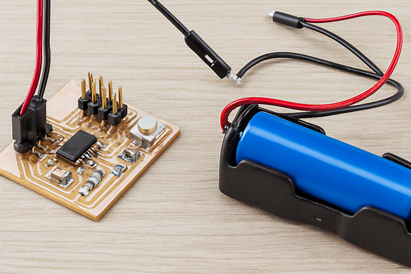
Hardware Connection
To program the board I made the following connections:
FabISP al computador mediante USB.
FabISP to PCB with ribbon cable (verifying GND was correctly aligned).
PCB al computador mediante cable FTDI.
Correct connection of the GND was critical. An error in this part can completely prevent programming.
This week I not only learned how to program a microcontroller; I understood that embedded programming requires precision, rigorous technical reading, and a deep understanding of the hardware.
Reading the datasheet completely changed my perspective: I no longer see the microcontroller as a “black chip”, but as a logical system with defined architecture, registers, timers and clear limitations.
Programming my own board and watching it respond was one of the most satisfying moments of the process.
Here I understood that electronics stops being theoretical when the code manages to control matter.