Computer Controlled Cutting
Semana 03:Computer-Controlled Cutting
Student: Cindy Marilyn Crispín Fab Lab: Fab Lab Huando Year: 2026
Group Assignment – Laser Cutter Characterization

In our digital manufacturing space we work with a high-precision CO₂ laser cutting machine, designed to materialize ideas with millimeter accuracy and high-quality finishes.
This technology allows us to cut and engrave wood, acrylic, plastics, leather, fabrics and other materials, transforming digital designs into real pieces quickly, cleanly and with a high level of detail.
The system combines speed, control and versatility, becoming a fundamental tool for the development of prototypes, personalized accessories and innovative projects.
Technical Characteristics of the CNC Laser Cutter
Dimensiones: 730 x 562 x 298 mm
Working area: 406 x 305 mm
Maximum part height: 114 mm
Laser power: 40W (CO₂ tube)
Manual focus with 2" lens
High Speed DC Servo Motors with Linear and Rotary Encoding
Working modes: Raster, vector or combined
Resolución ajustable: 75 – 1200 dpi
Alimentación: 110–240 V, 50/60 Hz, monofásica
Noise level: 59 dB
Peso aproximado: 40 kg
This configuration ensures sharp cuts, precise engravings, and stable performance for academic and professional prototyping processes.

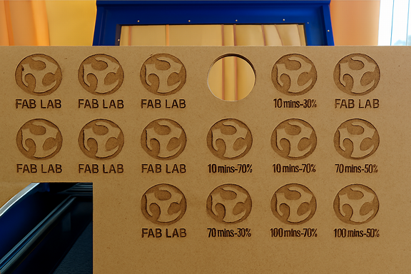
Laser Focus Calibration Pattern Design
Although the manufacturer includes a standard calibration pattern, a practical experience was developed to verify the actual working focal length and experiment with variations that optimize future projects.
The design was carried out in Fusion 360, generating five patterns with distances close to the value recommended by the manufacturer.
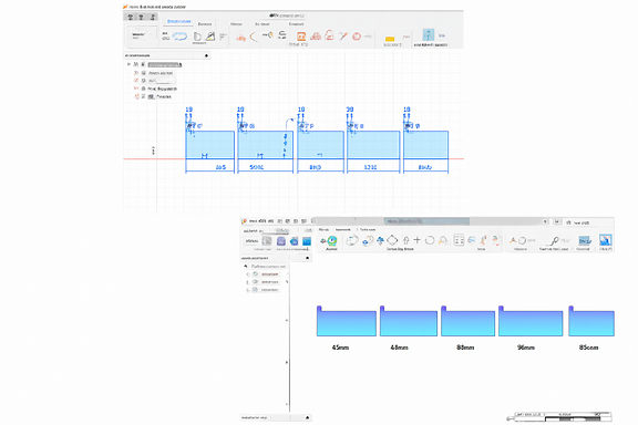
The objective was to evaluate how small variations in distance influence the quality of the cut.
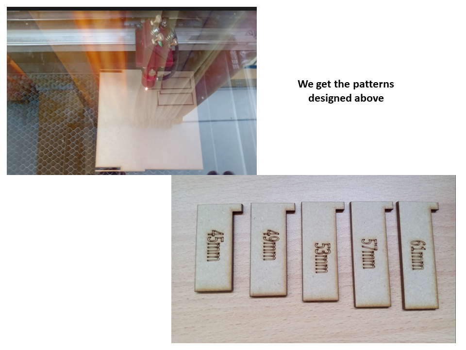
Calibration Process
For the test, 3 mm MDF was used as the base material.
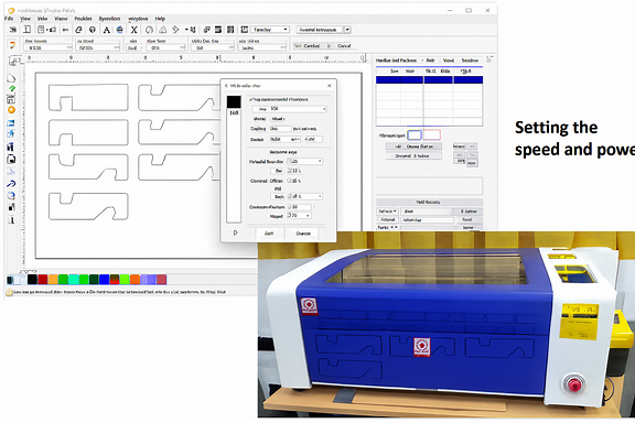
Parámetros utilizados:
Potencia: 30 %
Velocidad: 70 mm/s
The patterns obtained showed clear differences in the definition of the cut.
After the comparative analysis, it was determined that the optimal focusing distance is 53 mm, since it presents:
✔ Clean cut ✔ Well defined edges ✔ Minimum irregularities ✔ Better laser beam penetration
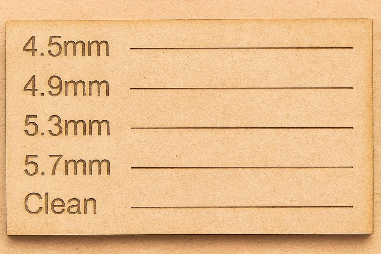
Power and Speed Patterns
Once the ideal distance of 53 mm was established, new patterns were developed by varying two fundamental parameters:
Velocidad
Potencia
The objective was to understand the relationship between both variables and their impact on the final result.
Analysis of Results
El estudio permitió concluir que:
To achieve deep, defined cuts, you need to slow down and increase the power.
For superficial engravings or light paths, it is advisable to use low powers, which also contributes to prolonging the life of the laser tube.
The appropriate balance between speed and power optimizes energy consumption and the final quality of the material.
This experimentation strengthens technical understanding of laser behavior and improves decision making in digital manufacturing processes.
📁 Project Files
Calibrador.f3d
These files document the design process and allow the patterns to be replicated or adjusted in future practices.
2️⃣ Individual Assignment – Parametric Construction Kit
Design Concept
I designed a parametric press-fit construction kit that allows multiple assembly configurations without glue.
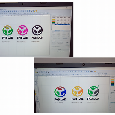
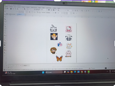
I go to Inskape to design my project and test the powers.
We change the work units to millimeters in the 3 lines where the name of the document is. I make a new sketch by right clicking in the new document area
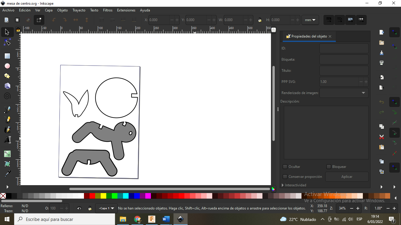
You choose circle by corner and then choose dimension to measure from vertex to vertex of the ellipse with a measurement of 360. We enter the squares with measurements of 20mm on each side and choose sketch rounding to 5mm, made another design with my name of 20cm x 20cm and we duplicate that row by 10 rows by right clicking on copy sketch entities and separating from row to row 5mm and from column to column 8mm

We also made another design of a rabbit-shaped table.
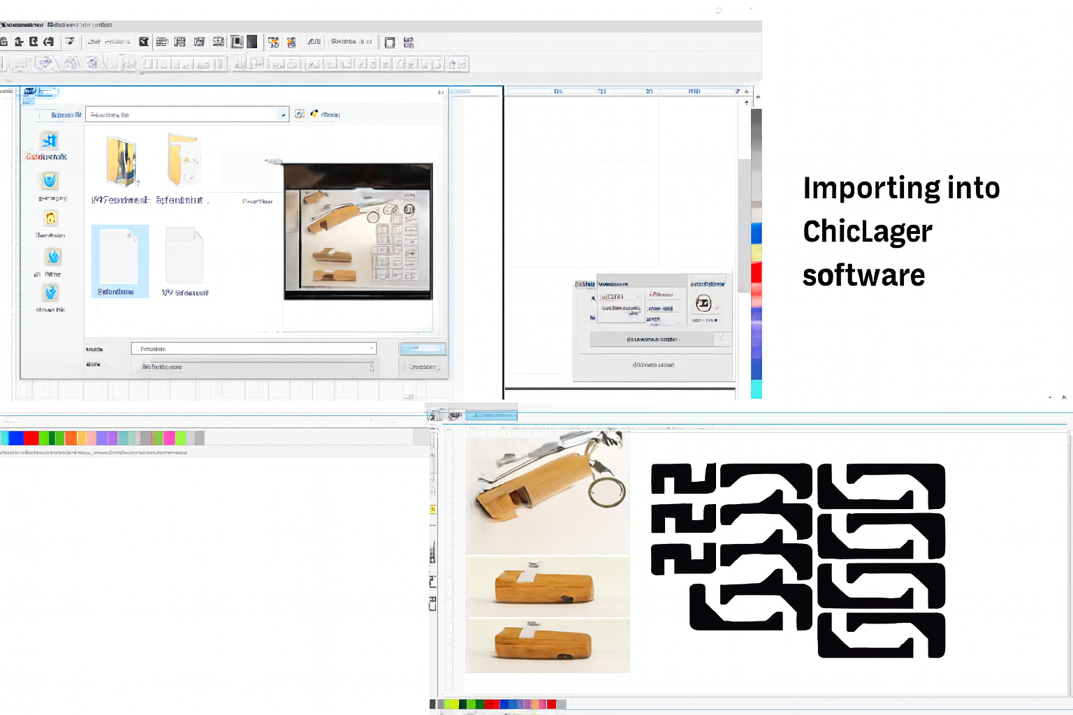
we export in dxf format
We open the laser CNC program and import the file
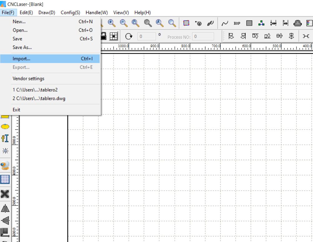
In this image we can see the exported file made previously in inskape
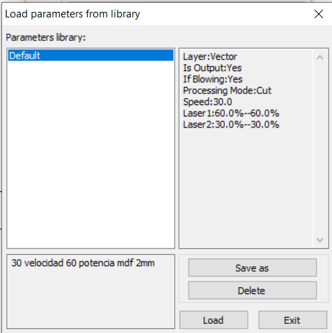
In this image we can load the default values to continue with the cut.
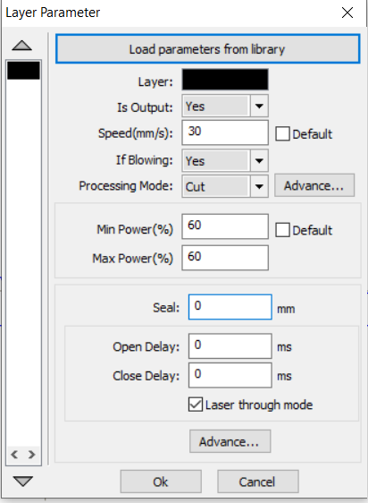
Once the values for the cut have been loaded, we proceed to press OK.
Gallery Design of a parametric drawing, cutting and assembly
In this week's assignment I will show advanced parametric design of a figure, working with the design in software and then printing it with a laser cutter.
Initially I began to design the lateral part of the figure with the measurements seen in the Inskape program.
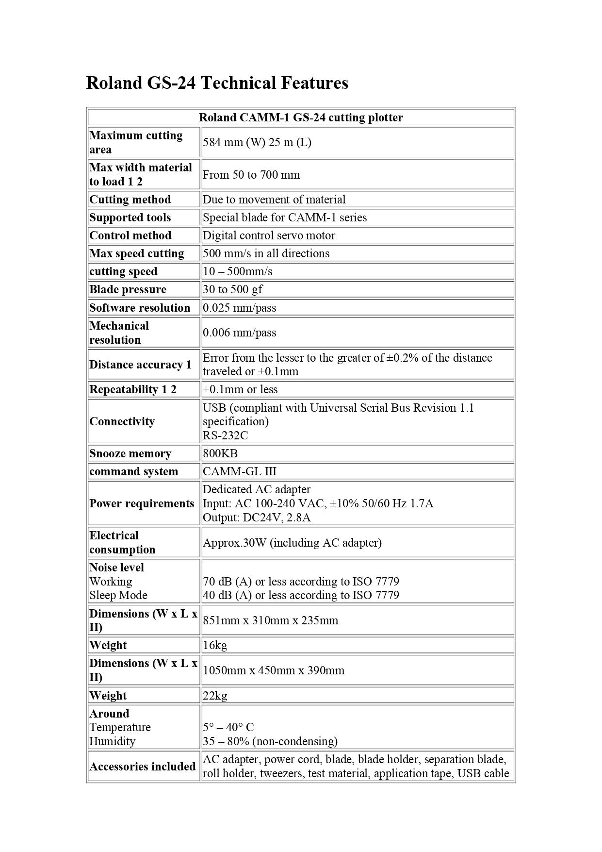
Vinyl Cutting Machine
Graphic precision applied to institutional identity
The vinyl cutting process was developed using the Roland CAMM-1 Servo GX-24, a high-precision machine widely recognized in digital manufacturing environments for its reliability and accuracy in layout.
The work was carried out with Roland CutStudio software, a tool that allows you to convert digital designs into vector paths ready for cutting, optimizing lines, curves and typographic details.
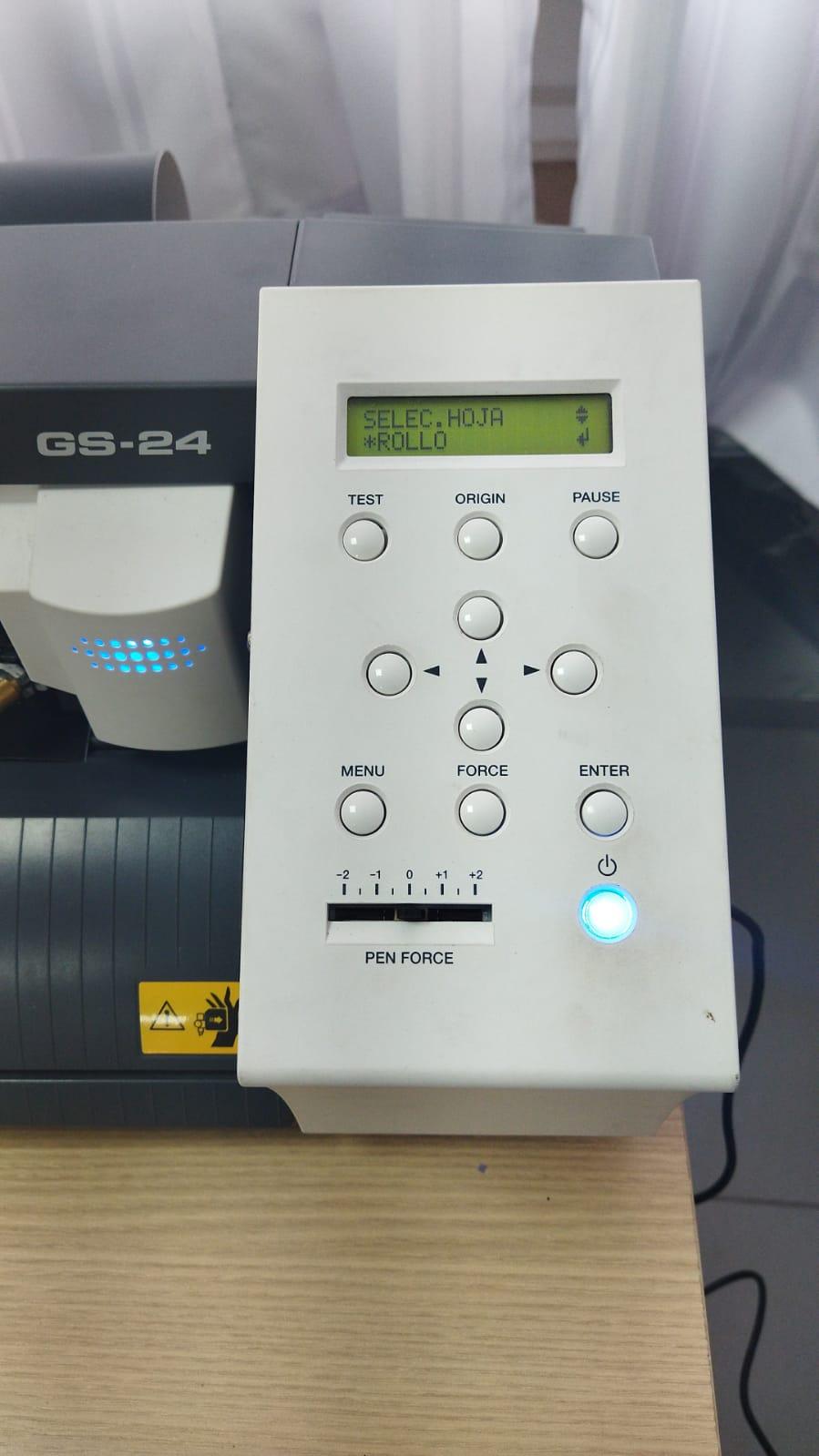
From the moment the device turns on and displays its active control panel, the machine is ready to transform a design into a tangible physical application. The clear and functional interface allows you to configure the material, adjust parameters and verify correct alignment before starting the process.
https://www.rolanddga.com/es-la/productos/software/roland-cutstudio-software
Design Preparation in CutStudio
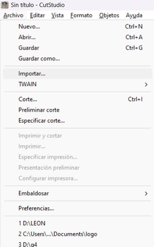
The workflow started with the import of the graphic file:
Archivo
Importar
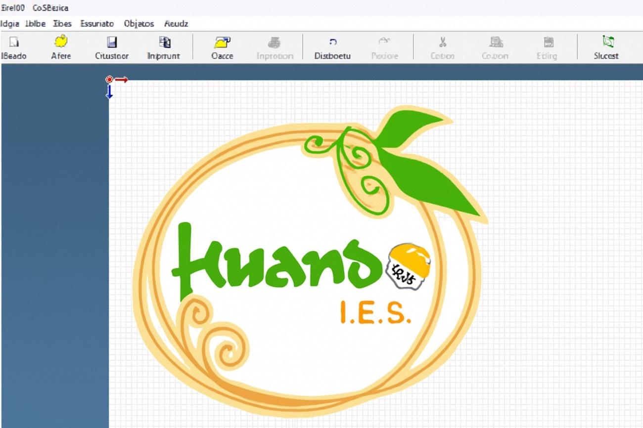
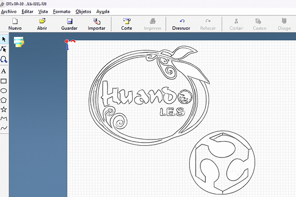
Design selection in JPG format
Once the image was loaded, the vectorization process was performed, extracting the contour lines to convert the raster image into cutting paths.
In this case we worked directly in the program:
The size and proportions were adjusted.
The preview of the material was checked before cutting.
Correct prior configuration ensures that the line is clean and continuous, avoiding incomplete or excessive cuts.
Cutting Process
With the material correctly placed in the Roland CAMM-1 GX-24, the cutting option was selected, which displayed the final settings window.
The team executed the layout with precision, faithfully following the lines generated in the software. The combination of mechanical calibration and digital tracing allowed us to obtain defined cuts, without damaging the vinyl base support.
Application in the Institutional Environment
As part of the practical process, the designs were applied in the Academic Secretariat of the institution, strengthening the visual identity of the space.
In addition, the institutional name and the digital manufacturing logo were placed on one of the furniture in the area, evidencing how cutting technology can be integrated into real projects to improve the educational environment.
This experience not only allowed us to understand the technical operation of the machine, but also demonstrated its potential to transform spaces through applied graphic design.
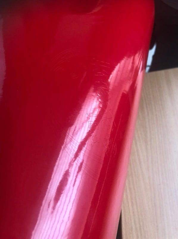
Post-Proceso (Weeding y Transferencia)
Once the cut is finished:
The lines were carefully checked to ensure that the cut was complete.
The excess material was removed manually (a process known as weeding).
Even discarded parts were preserved that could be reused in future projects.
The figure was transferred to the destination, applying it carefully to avoid bubbles or misalignments.
Finally, evidence of the completed work was left on the Roland machine where it was produced, closing the complete cycle: design → cutting → application.
Archivos Utilizados
File 7: Processing in CutStudio
File 8: Parametric Design Kit
These files document the process from digital conception to final materialization.