3d Scanning Printing
Semana 05:
3D Scanning and Printing
(Fab Academy 2026 – Scanning and 3D Printing)
GROUP ASSIGNMENT
Testing the Design Rules of the 3D Printer
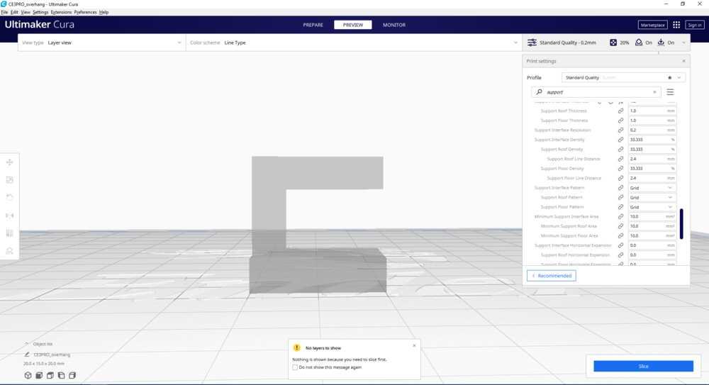
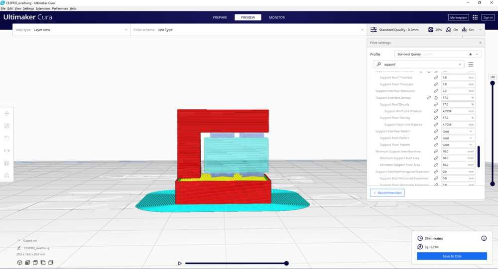
As a group, we analyzed and tested the design rules of an FDM 3D printer to understand its capabilities and limitations.
We evaluated:
Minimum wall thickness
Overhang angles
Bridging distance
Tolerance between parts
Layer adhesion
First layer calibration
Support requirements
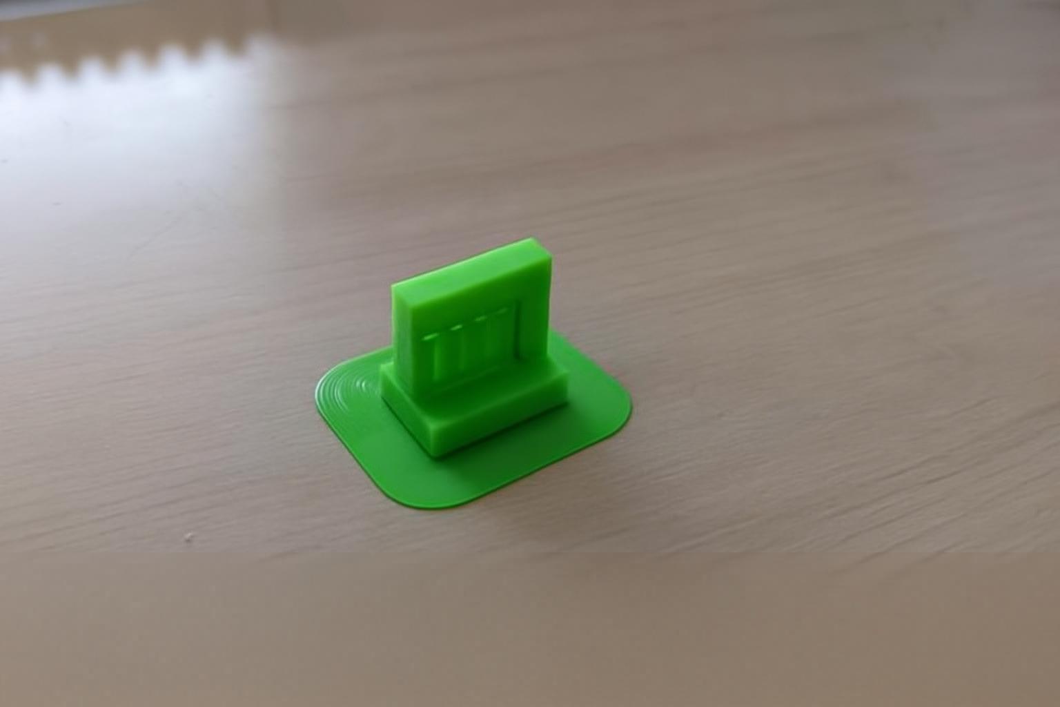
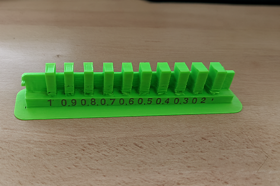
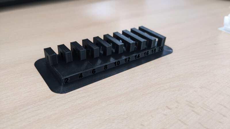
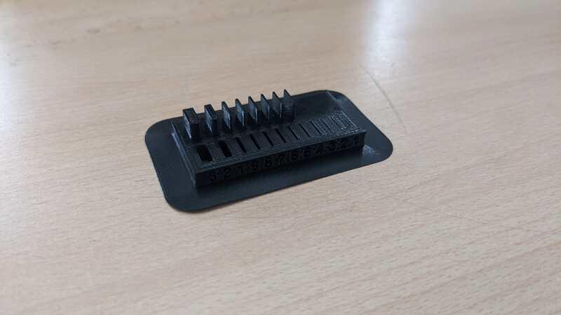
Design Rule Tests
We prepared standard test geometries including:
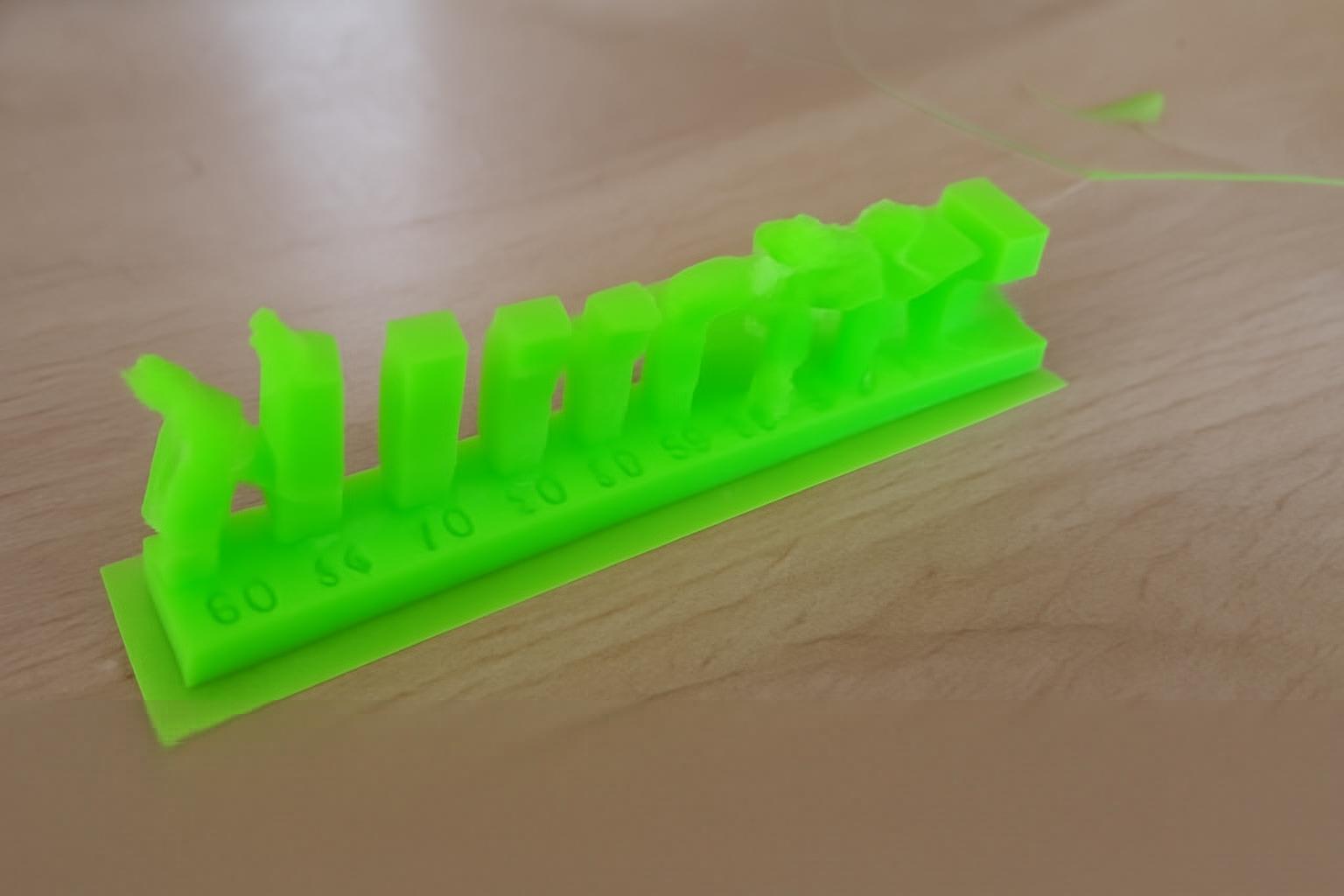
Overhang test (angles from 30° to 75°)
Bridging test
Tolerance clearance test
Thin wall test
Soportes
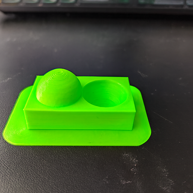
In the Digital Manufacturing laboratory of IES Huando, 3D printing tests were carried out with the aim of analyzing the behavior of different geometries when printing with and without supports.
The purpose was to understand how configuration parameters influence the final quality of the part, especially in cases of overhangs, bridges and clearances (liquidation), as well as to evaluate the ease of removal of the support material.
Printer Settings (Ender 3)
Printer Settings (With Support)
For the first tests, the use of supports with the following parameters was activated:
Perfil: 0,2 mm
Relleno: 20%
Soporte: Activado
Printing temperature: 215°C
Bed Adhesion: Edge (Brim)
Impresora: Ender 3
The use of support was necessary in designs with pronounced overhangs and clearances, since, without an auxiliary structure, the molten material tends to move towards the nearest surface, affecting the precision and finish of the part.
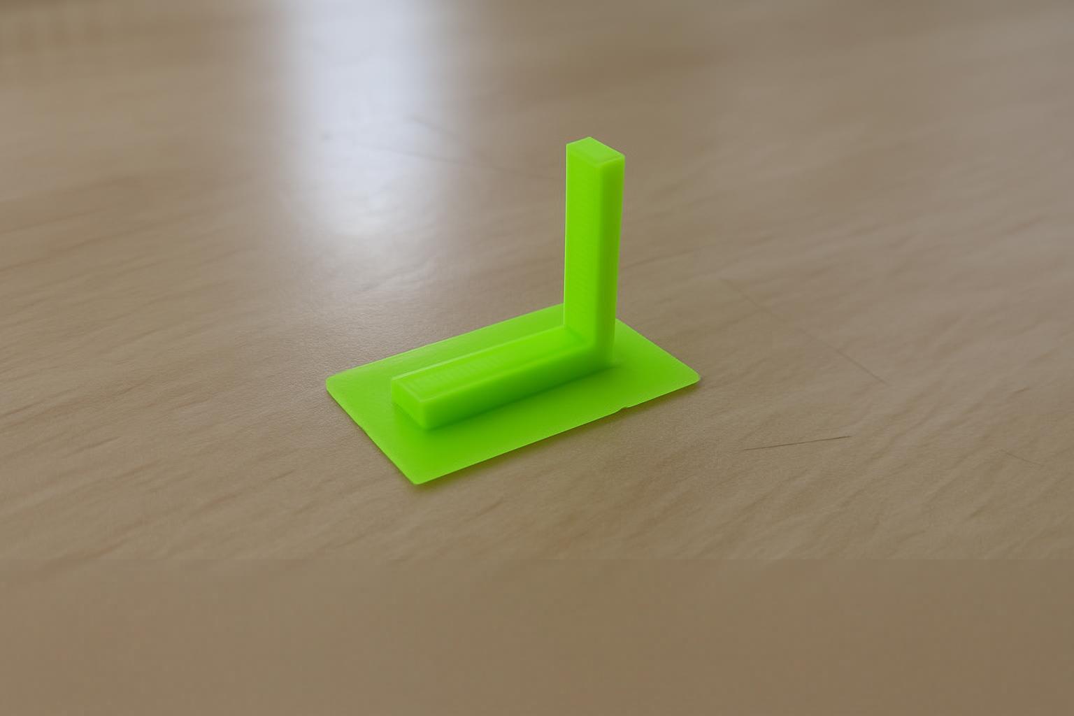
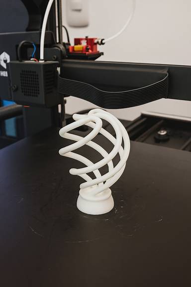
Voladizo
A steeply tilted model was printed to assess the need for support.
Con soporte: mejor estabilidad y definición.
Without support: deformation and fall of the material.
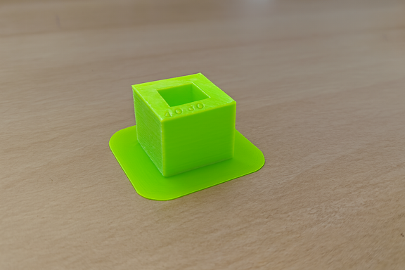
Liquidación (Espacio libre)
The separation between pieces or internal cavities was analyzed.
Con soporte: estructura estable.
Without support: partial collapse of the roof.
Configuración sin soporte
In the second test, the supports were deactivated, keeping the other parameters the same:
Perfil: 0,2 mm
Relleno: 20%
Soporte: Desactivado
Temperatura: 215 °C
Adhesión: Borde
The objective was to directly compare the results and demonstrate the importance of the support in certain geometries.
5. Otras pruebas geométricas
Additional tests were also carried out to analyze other important factors in 3D printing.
Ángulo
Evaluation of the tilt limit without the need for support.
🔹 Puente
Print test between two separate points without intermediate support.
wall thickness
The resistance and structural stability were analyzed according to the configured thickness.
Dimensiones
Verification of dimensional accuracy and tolerances.
Anisotropía
The mechanical resistance was evaluated according to the printing orientation, observing differences in the force applied in different axes.
Acabado superficial
The external texture was analyzed according to layer configuration and thermal parameters.
Relleno
Comparison of resistance and material consumption with 20% infill.
Support Optimization
Three attempts were made to configure the support to facilitate its removal:
🔹 Primer intento
It was configured with greater density and less separation between the model and the support. Result: Difficult to remove, risk of damaging the piece.
Segundo intento
The distance between contact layers was slightly reduced. Result: Removal improved, but still presented difficulty.
Tercer intento (Configuración óptima)
The contact material between support and model was decreased, adjusting the distance Z of the support. Result: ✔ Easy removal ✔ Better surface finish ✔ Lower risk of damage
It is concluded that the greater the number of lines or layers of contact between the support and the design, the greater the difficulty of removal. A balanced configuration allows for stability during printing and ease in post-processing.
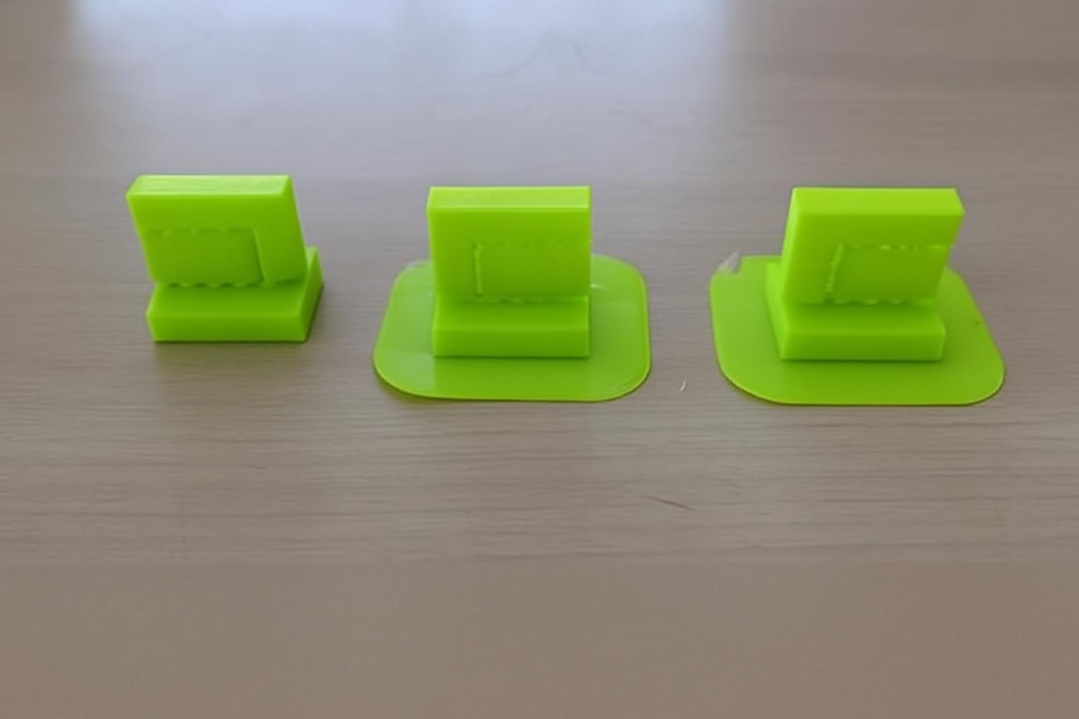
The result was that it was easy to remove the support.
Conclusiones
The tests carried out at the IES Huando allowed us to verify that:
Supports are essential in geometries with pronounced overhangs and clearances.
The correct configuration of the support directly influences the final finish.
Not all parts require support; It depends on the angle and design.
Proper adjustment reduces post-processing time and prevents damage to the part.
Experimentation is key to mastering 3D printing.
https://academy.cba.mit.edu/classes/scanning_printing/index.html
Observed Printer Limits (FDM – 0.4mm nozzle)
Minimum reliable wall thickness: 0.8 mm
Overhangs above 60° require supports
Tolerance under 0.3 mm may fuse
Bridging works up to 15–20 mm
First layer calibration is critical for adhesion
What I Learned
Additive manufacturing requires design adaptation.
Small dimensional differences significantly affect assembly.
Cura preview is essential to detect failures before printing.
Supports must be minimized through intelligent design.
INDIVIDUAL ASSIGNMENT
Tarea Individual
To develop this activity I used the Fusion 360 program to create a sphere inside a cube through modeling and revolution operations.
First I created a 50 millimeter square in a new sketch. Later I applied the extrusion tool, giving it a height of 25 millimeters to form the cube.
I then generated a new sketch on one of the faces and drew a circle. I applied the extrusion using the cut option (Delete/Remove) and selected the second end position so that the cut went completely through the solid.
If we rotate the model in three-dimensional view, we can observe the internal modification generated by the operation.
Again I created another sketch, setting a distance of 48 millimeters as a reference. I drew another circle and repeated the extrusion process with the full cut option and second end position.
I repeated the procedure once more to achieve the desired internal shape.
I then created a circle inside the 50 millimeter cube and set the axis of revolution inline to generate the internal spherical shape.
Finally, I changed the color of the solid to differentiate the surfaces and improve the visualization of the model.
Preparation of the file for 3D printing
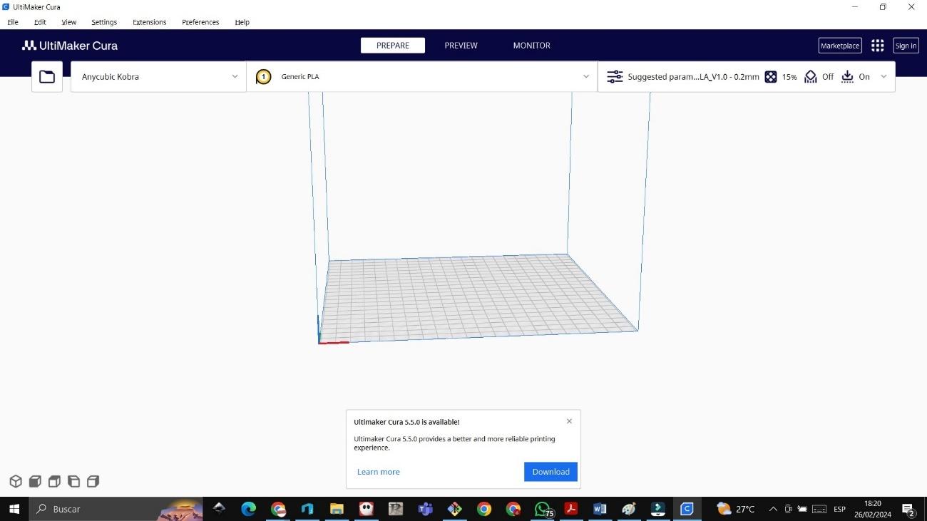
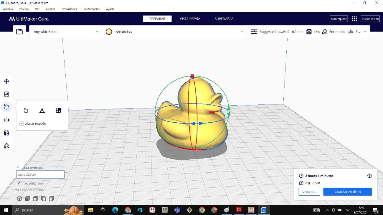
I exported the file in STL format and went to the official Ultimaker Cura website to download the software.
I installed the program and configured the Bestgee T300S printer.
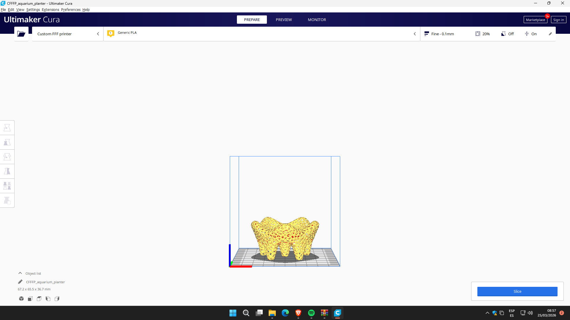
I imported the STL file into Ultimaker Cura. Within the software I modified the dimensions, reducing the size to 70%, obtaining an estimated printing time of 2 hours and 11 minutes.
Printing process with Bestgee T300S
I turned on the Bestgee T300S 3D printer and verified that the bed was clean and properly leveled.
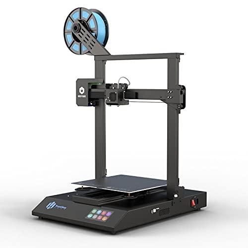
The extruder was heated to 200 °C and the hot bed to 60 °C to work with PLA filament.
I performed the leveling by adjusting the Z axis (Z-offset), leaving approximately 1 millimeter of clearance on the bed and checking the calibration with a sheet of paper.
I placed the PLA filament in the extruder until I verified that it was flowing correctly and finally started printing.
The print was tested in the laboratory, obtaining a satisfactory result.
Set the z axis with a 1 millimeter gap between the bed and the extruder.
The x and y axes were set automatically.
The material used was 1.75 millimeter PLA from León brand.
The bed was expected to heat up to 60 degrees and the extruder to 200 degrees.
The work area was 20 x 25 centimeters.
Archivo stl
Regarding the software used, it was Cura, having to search between several printer options to which it was connected.
3D Object Scan
For the scanning process I used the Matter and Form 3D scanner along with the MFStudio software, which allows direct communication between the hardware and the laptop.
Scanner Calibration
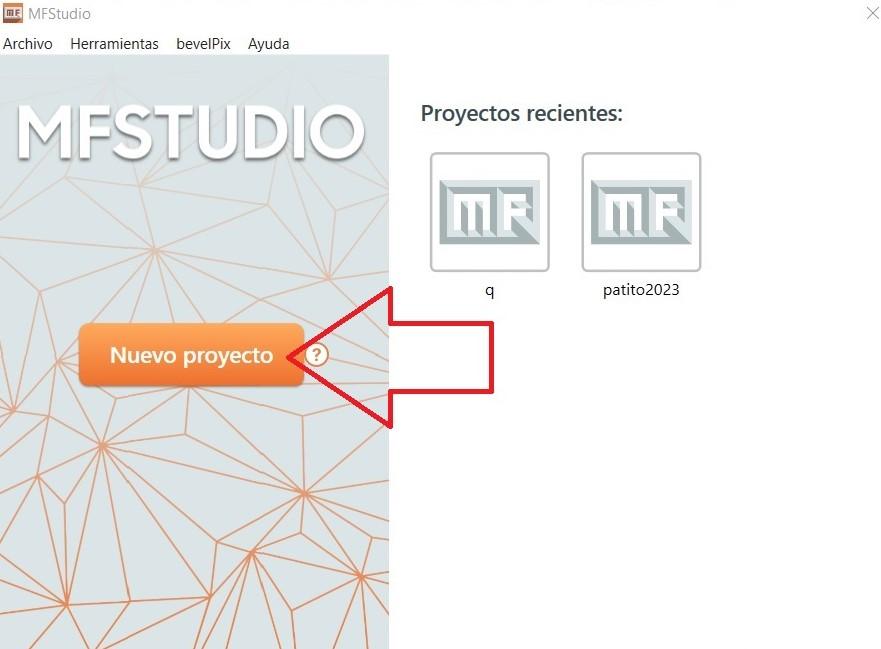
First I opened the MFStudio program and selected the “New Project” option to start the scanning process.
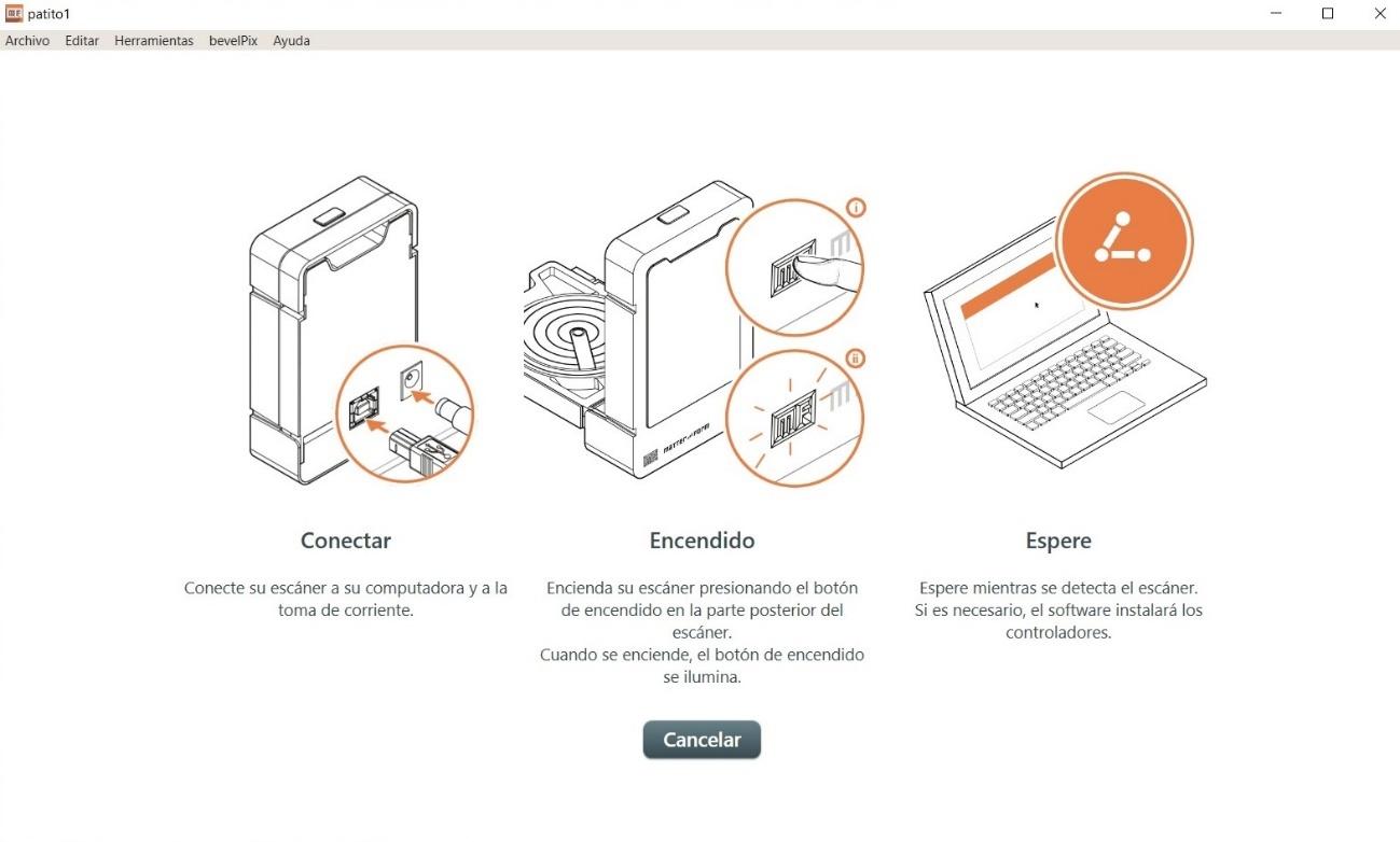
Later I prepared the equipment, connecting the scanner to the power supply and to the laptop using the USB cable. I verified that the device was correctly recognized by the software before continuing.
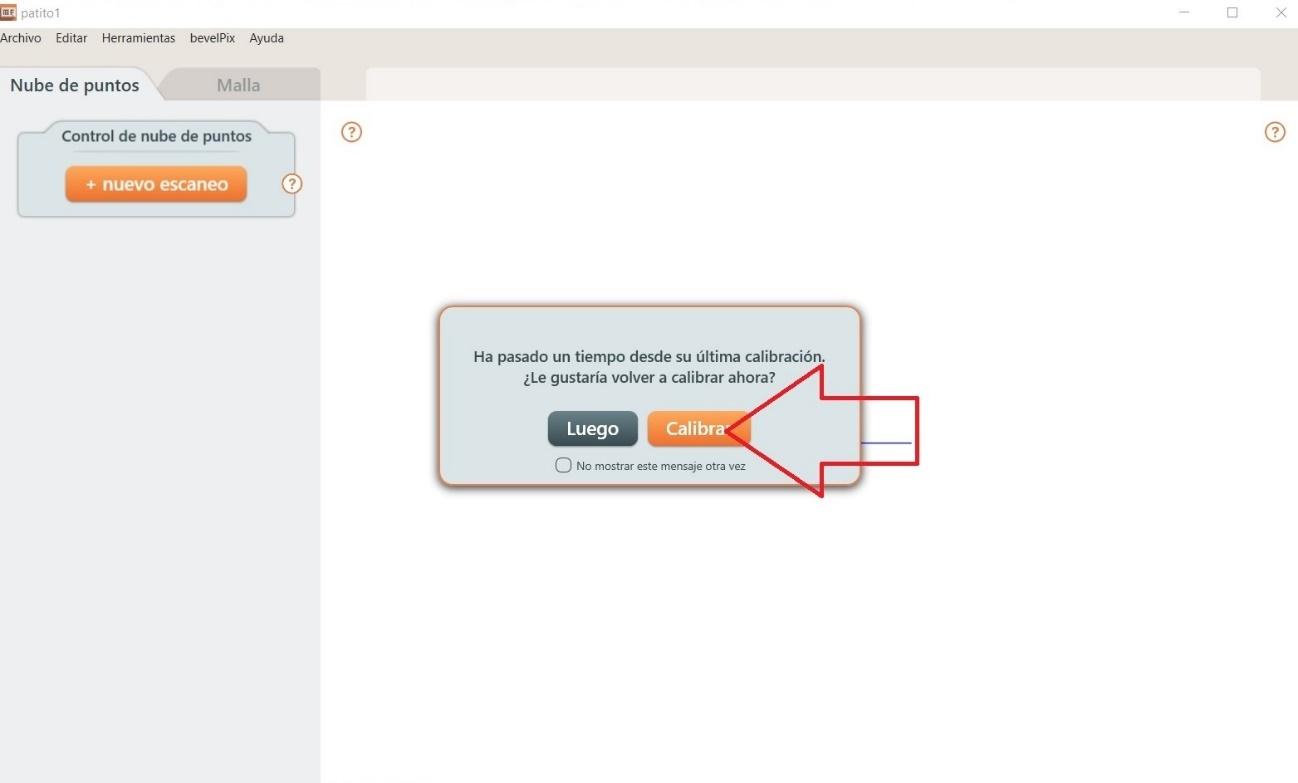
As the next step, I selected the “Calibrate” option, since this procedure is essential to ensure that the scan has accuracy in dimensions, alignment and depth.
For automatic calibration, I placed the board of small black and white squares in front of the scanner, as indicated in the equipment manual. This board allows the system to recognize the geometric patterns necessary to properly adjust light, distance and focus.
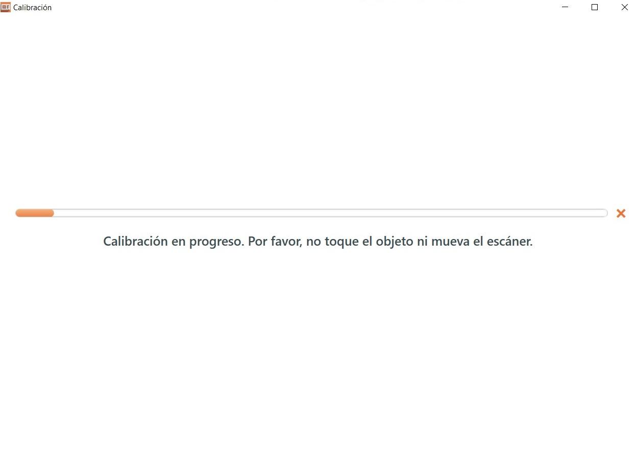
During the process, the scanner projected lines of light that moved horizontally and vertically onto the calibration plate. This allowed the system to adjust the light intensity and alignment of the optical sensors.
I waited a few minutes until the software confirmed that the calibration had completed successfully.
Scanning process
Once the equipment was calibrated, I placed the black pyramid-shaped object in the center of the scanner's rotating base. It is important to correctly center the object to avoid deformations or loss of information at the edges.
When I started the scan, I observed that the lines projected on the surface of the pyramid allowed the volumes and edges to be captured. However, in a first test I noticed that some lines came out misaligned due to the dark color of the object and the inclined geometry of its faces.
Therefore, I reconfigured the scanner by adjusting parameters such as exposure and capture sensitivity, which allowed me to improve the definition of the edges.
During the process, the point cloud that was progressively generated could be viewed on the screen. This point cloud represents the spatial information captured by the scanner.
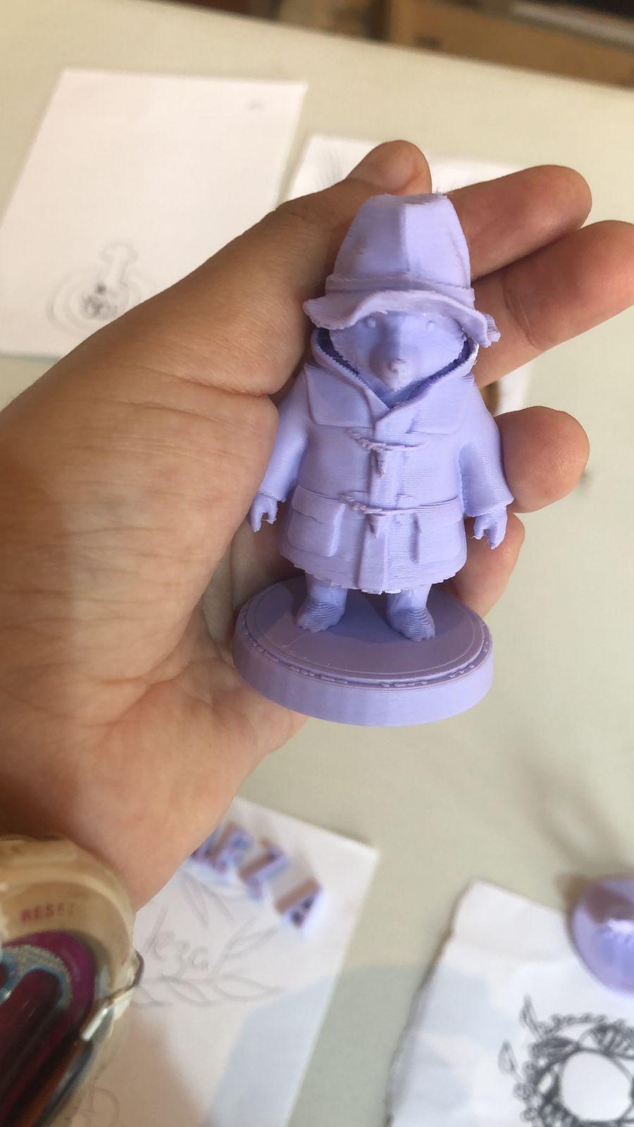
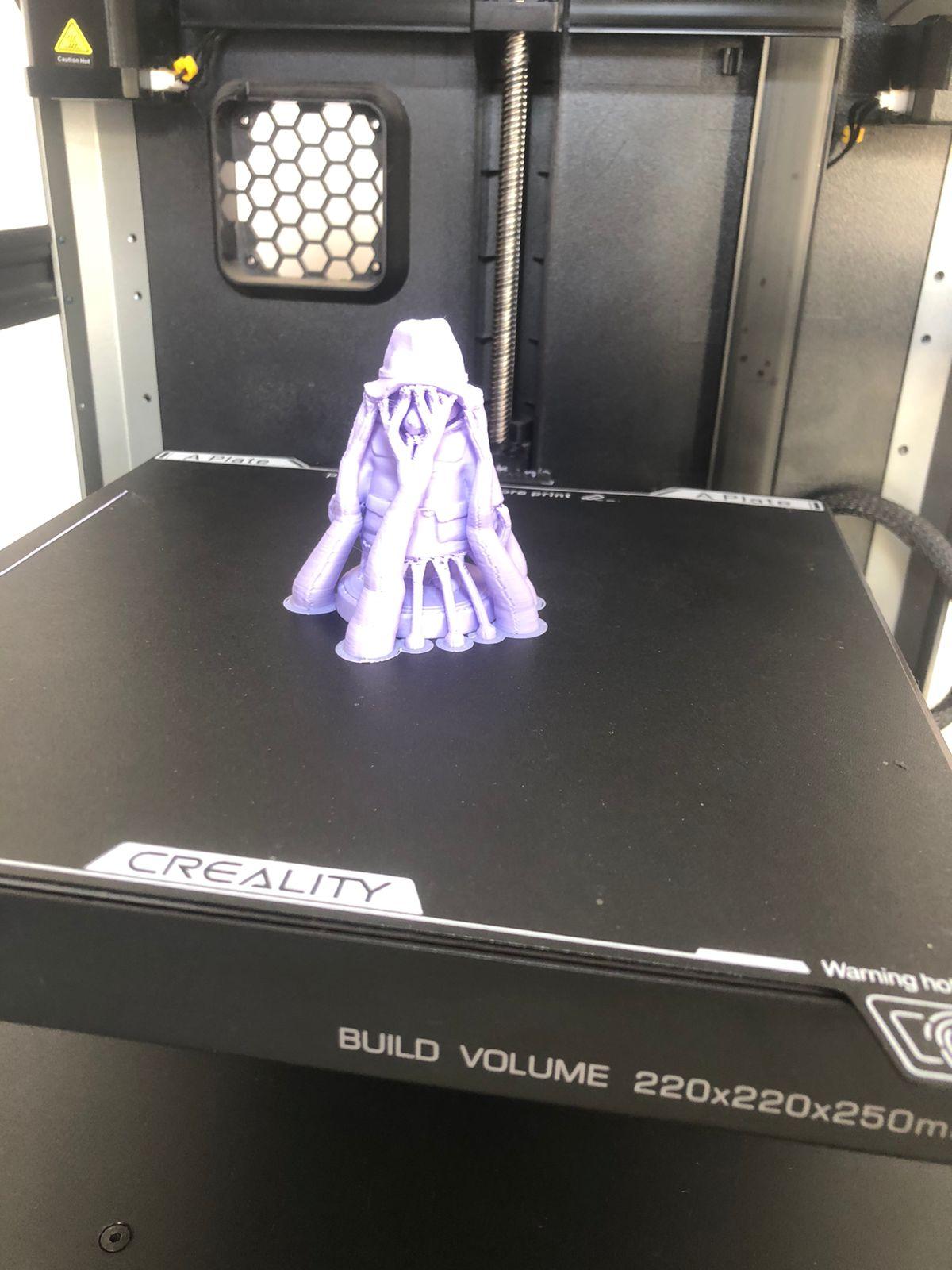
otros diseñitos….
También imprimi un osito padintong
Upon completion, the software performed automatic meshing, transforming the point cloud into a three-dimensional solid surface.
Preparation for 3D printing
Once the digital model was obtained, I exported the file in STL format for later printing.
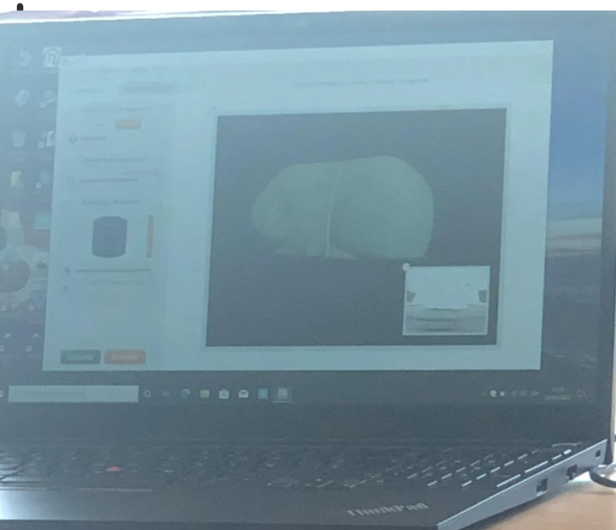
I opened the file in the laminating software and verified that the dimensions were correct. I then centered it on the virtual print bed and generated the corresponding G-code.
During 3D printing, the layered construction process could be observed. The base of the pyramid was printed first, ensuring good adhesion to the hot bed. Later, the inclined faces were formed until the structure was completed.
In the final stage it was verified that the print was completely finished and that the edges maintained a defined and stable shape.
Comparación y análisis
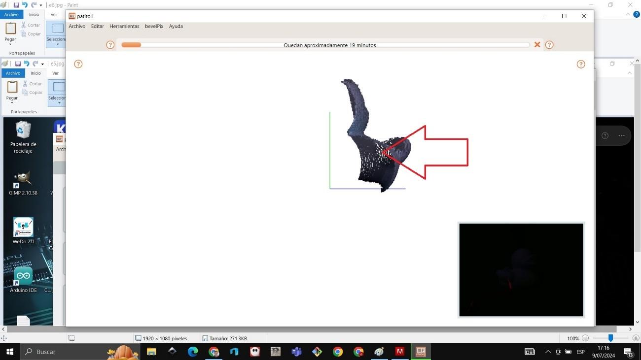
Finally, I made a comparison between the original object, the scanned model and the 3D printed part.
It could be seen that the scan managed to reproduce the general geometry of the object quite accurately. However, small variations were evident in areas that were difficult to access or on the most pronounced edges, which is common in optical scanning processes.
This exercise allowed me to understand the importance of correct calibration, as well as the influence of the color, texture and lighting of the object on the quality of the scan.
Conclusiones
In this activity I learned how to model solids in Fusion 360 using extrusion, cutting and revolution.
I learned how to prepare files in STL format for 3D printing.
I learned how to use the Ultimaker Cura software and how to properly configure the Bestgee T300S printer.
I learned how to calibrate the bed, adjust the Z axis, and place the PLA filament.
Additionally, I learned to scan small objects using photogrammetry and 3D scanning, understanding the point cloud and meshing process.